
Structure for use in piezoelectric element, braided piezoelectric element, fabric-like piezoelectric element using braided piezoelectric element, and device using these

A technology of piezoelectric elements and structures, applied in the measurement of the force of piezoelectric devices, the manufacture/assembly of piezoelectric/electrostrictive devices, electrical components, etc., can solve problems such as lack of flexibility

Active Publication Date: 2019-06-04
TEIJIN FRONTIER CO LTD +1
View PDF10 Cites 1 Cited by
  • Summary
  • Abstract
  • Description
  • Claims
  • Application Information

AI Technical Summary

Problems solved by technology

However, since it is in a sheet shape, it is not possible to use it in such a way that it can bend freely like cloth because it lacks flexibility.

Method used

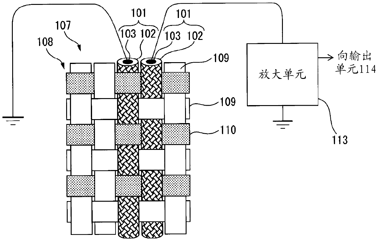
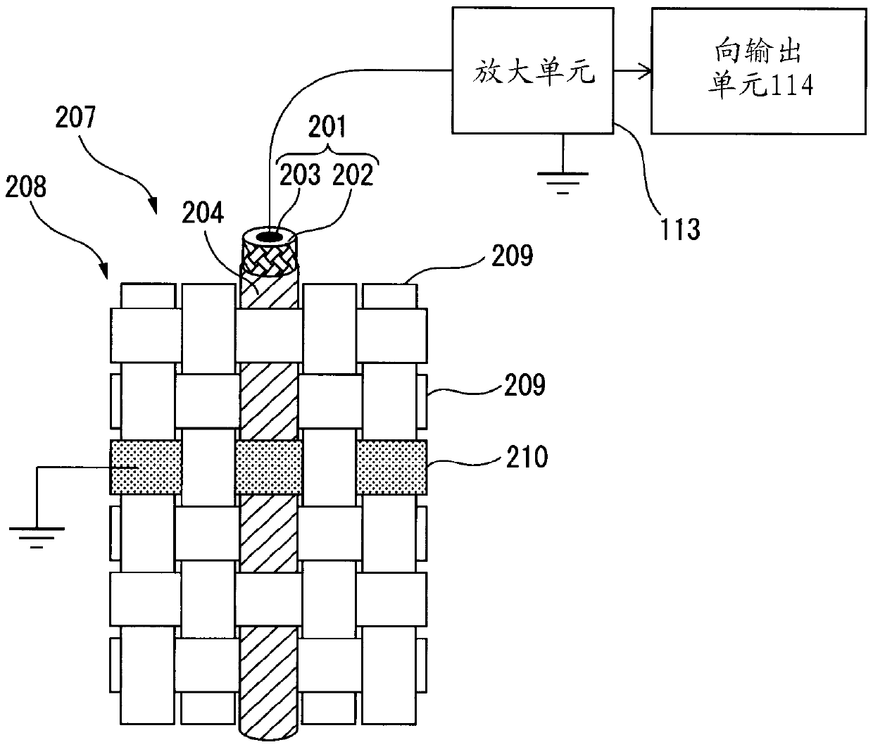
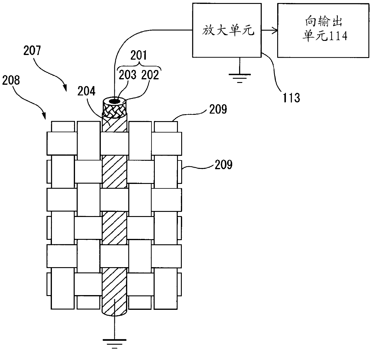

Image

  • Structure for use in piezoelectric element, braided piezoelectric element, fabric-like piezoelectric element using braided piezoelectric element, and device using these
  • Structure for use in piezoelectric element, braided piezoelectric element, fabric-like piezoelectric element using braided piezoelectric element, and device using these
  • Structure for use in piezoelectric element, braided piezoelectric element, fabric-like piezoelectric element using braided piezoelectric element, and device using these

Examples


Embodiment 1)

[0585] In the present example, regarding the piezoelectric elements used in the first to third inventions, the effect of the orientation angle θ of the piezoelectric polymer and the value of T1 / T2 on the electric signal for the expansion and contraction deformation was investigated. influences.

[0586] (Example A)

[0587] As a sample of Example A, such as Figure 10As shown, the conductive fiber CF1 is used as the core wire, and the above-mentioned piezoelectric fiber PF1 is placed on the 4 carriers woven along the Z-twist direction among the 8 carriers of the 8-ply round rope rope making machine. The above-mentioned insulating fiber IF1 is woven on four carriers woven in the S-twist direction to produce a cord in which the piezoelectric fiber PF1 is helically wound in the Z-twist direction around the core wire. Shaped piezoelectric element 1-A.

[0588] (Example B)

[0589] Using the rope-shaped piezoelectric element 1-A as the core wire, the above-mentioned four carrie...

Embodiment 2)

[0618] In this example, in the second invention and the third invention, regarding the piezoelectric element that can be used together with the piezoelectric element of Example 1, in particular, the orientation angle θ and T1 / T2 of the piezoelectric polymer were investigated. The effect of the value of on the electrical signal for warping deformation.

[0619] (Example AA)

[0620] As the sample of Example 1, such as Figure 10 As shown, using the conductive fiber CF1 as the core wire, all of the 4 carriers woven in the Z twist direction and the 4 carriers woven in the S twist direction among the 8 carriers of the 8-ply round rope rope making machine The above-mentioned piezoelectric fiber PF1 is set and braided, thereby producing a rope-shaped piezoelectric fiber in which the piezoelectric fiber PF1 is wound helically in both the Z-twist direction and the S-twist direction around the core wire. Element 1-AA.

[0621] (Example AB)

[0622] The rope-shaped piezoelectric ele...

Embodiment 3)

[0651] The fabric for piezoelectric elements of the second invention is produced by the following method.

[0652] (Manufacture of polylactic acid)

[0653] The polylactic acid used in the examples was produced by the following method.

[0654] Add 0.005 parts by mass of tin octoate to 100 parts by mass of L-lactide (manufactured by Musashino Chemical Research Institute, optical purity 100%), and react at 180°C with a reactor equipped with stirring blades under a nitrogen atmosphere After 2 hours, 1.2 times the equivalent of phosphoric acid was added to tin octoate, and then the remaining lactide was removed under reduced pressure at 13.3 Pa, and poly-L-lactic acid (PLLA1) was obtained by chipping. The obtained PLLA1 had a mass average molecular weight of 152,000, a glass transition temperature (Tg) of 55°C, and a melting point of 175°C.

[0655] (piezoelectric fiber)

[0656] PLLA1 melted at 240° C. was poured out from the 24-well lid at 22 g / min and retrieved at 1300 m / mi...


PUM

PropertyMeasurementUnit
lengthaaaaaaaaaa
diameteraaaaaaaaaa
diameteraaaaaaaaaa

Abstract

Provided is a structure having an oriented piezoelectric polymer arranged into a cylindrical or columnar shape, wherein the oriented angle of the oriented piezoelectric polymer is 15-75 degrees with respect to the center axis of the structure, the piezoelectric polymer includes a crystal polymer of which the absolute value of piezoelectric constant d14 is 0.1-1000 pC / N when the oriented piezoelectric polymer has three orientation axes, and include a P body containing a crystal polymer of which the value of piezoelectric constant d14 is positive and an N body containing a crystal polymer of which the value of piezoelectric constant d14 is negative, and, when, in a part having a 1 cm length in the center axis of the structure, the mass of the P body in which the orientation axis is spirallywound in a Z twisting direction is defined as ZP, the mass of the P body in which the orientation axis is spirally wound in an S twisting direction is defined as SP, the mass of the N body in which the orientation axis is spirally wound in the Z twisting direction is defined as ZN, the mass of the N body in which the orientation axis is spirally wound in the S twisting direction is defined as SN,and, of (ZP+SN) and (SP+ZN), the smaller one is defined as T1 and the larger one is defined as T2, the value of T1 / T2 is 0 to 0.8. Also provided are a braided piezoelectric element and a fabric-like piezoelectric element each using the structure.

Description

technical field [0001] The present invention relates to a structure for a piezoelectric element, a cord-shaped piezoelectric element in which a cord using piezoelectric fibers is covered with a conductive layer, a fabric-shaped piezoelectric element using the cord-shaped piezoelectric element, and its use. their equipment. Background technique [0002] Conventionally, many technologies related to elements using piezoelectric substances have been disclosed. For example, Patent Document 1 discloses that an element in which a piezoelectric polymer is coated on a conductive fiber is superior in electrical response to friction. In addition, Non-Patent Document 1 discloses an example of an electrical response to an element in which a piezoelectric polymer is wound into a coil according to axial expansion and contraction of the coil and twisting deformation of the coil axis. Document 2 discloses a fibrous material made of a piezoelectric polymer, and it is described that the fibr...

Claims


Application Information

Patent Timeline
Patent Type & Authority Applications(China)
IPC IPC(8): H01L41/087D02G3/04D02G3/38D03D15/00G01L1/16G06F3/01G06F3/041H01L41/193H10N30/60H10N30/00H10N30/01H10N30/098H10N30/30H10N30/80H10N30/857H10N30/88
CPCD02G3/04D02G3/38D03D15/00G01L1/16G06F3/01G06F3/041D03D15/47D03D15/41D03D15/283D03D15/292H10N30/60H10N30/302H10N30/857H10N30/098H10N30/702D04B1/16D04B1/22D04B21/16D04B21/20D04C1/02D04C1/12D10B2401/18G01B7/16H10N30/802H10N30/883H10N30/30
Inventor 田实佳郎兼松俊介小野雄平
Owner TEIJIN FRONTIER CO LTD
Learn More