MEMS ultrasonic positioning sensor with Helmholtz resonant cavity

An ultrasonic positioning and sensor technology, which is applied in the direction of the fluid using vibration, can solve the problems of large size, low resonance frequency, poor resolution, etc.

Active Publication Date: 2020-01-14
武汉敏声新技术有限公司
View PDF12 Cites 3 Cited by
  • Summary
  • Abstract
  • Description
  • Claims
  • Application Information

AI Technical Summary

Problems solved by technology

Its advantage is high resolution, but the measurement distance is short. In addition, when the device size is small, the resonant frequency of the Helmholtz resonator cavity and the resonant frequency of the piezoelectric stack layer are difficult to match, so the size of this type of sensor is usually large , and the resonant frequency is low when working, resulting in poor resolution at close range
At the same time, in order to achieve the best receiving effect, the resonant frequencies of the receiving sensor, transmitting transducer, and Helmholtz resonator are usually set to be the same, but at this time, crosstalk will occur when sending and receiving sound waves

Method used


Image

  • MEMS ultrasonic positioning sensor with Helmholtz resonant cavity
  • MEMS ultrasonic positioning sensor with Helmholtz resonant cavity
  • MEMS ultrasonic positioning sensor with Helmholtz resonant cavity

Examples


Embodiment Construction

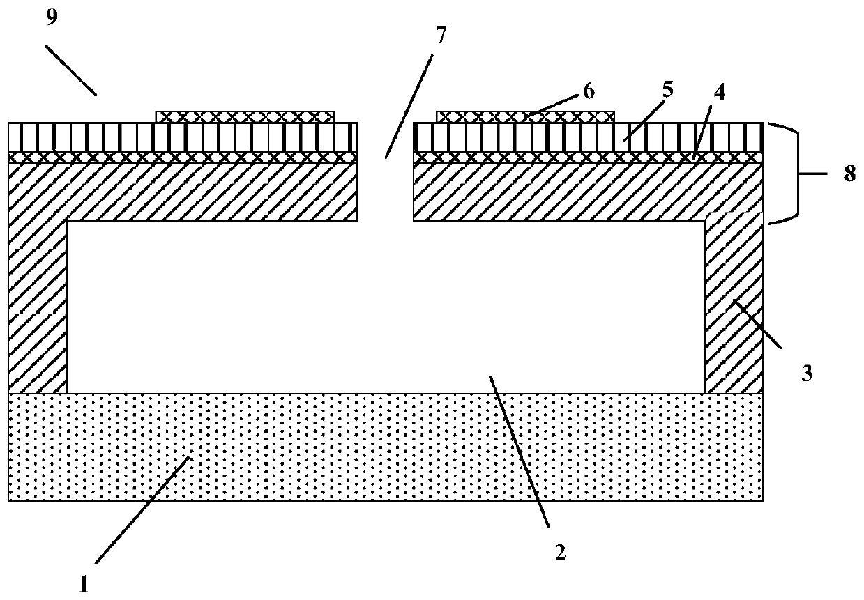
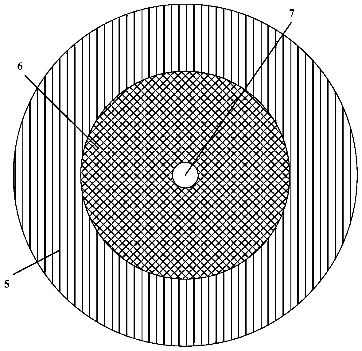
[0029] figure 1 A cross-sectional view of a MEMS ultrasonic positioning sensor with a Helmholtz cavity is shown according to one embodiment of the present disclosure. figure 2 show figure 1 Top view of the MEMS ultrasonic positioning sensor shown. Such as figure 1 , 2 , the MEMS ultrasonic transducer with a Helmholtz resonant cavity includes an ultrasonic receiving unit 1 , a Helmholtz resonant cavity 2 , and a piezoelectric ultrasonic transmitting unit 9 . The Helmholtz resonant cavity 2 is formed in an upper substrate 3 made of Si. The shape of the Helmholtz resonator 2 can be circular, square, rectangular or other geometric shapes. The piezoelectric ultrasonic transmitting unit 9 is located on the upper substrate 3 and has at least one through hole 7 communicating with the Helmholtz cavity 2 . The ultrasonic receiving unit 1 is located at the bottom of the Helmholtz cavity 2 . Wherein, the resonant frequency of the Helmholtz cavity 2 is the same as that of the piezo...


PUM


Abstract

The invention discloses an MEMS ultrasonic positioning sensor. The MEMS ultrasonic positioning sensor comprises an upper layer substrate (3), a Helmholtz resonant cavity (2) formed in the upper layersubstrate (3), a piezoelectric ultrasonic emission unit (9) located on the upper layer substrate (3), an ultrasonic receiving unit (1) located at the bottom of the Helmholtz resonant cavity (2), wherein at least one through hole communicating with the Helmholtz resonant cavity (2) is formed in the piezoelectric ultrasonic emission unit (9), the resonant frequency of the Helmholtz resonant cavity (2) is the same as that of the piezoelectric ultrasonic emission unit (9), and the resonant frequency of the ultrasonic receiving unit (1) is greater than or equal to that of the piezoelectric ultrasonic emission unit (9). The MEMS ultrasonic positioning sensor can improve the energy conversion efficiency of the sensor and avoid crosstalk of the sensor.

Description

technical field [0001] The disclosure belongs to the technical field of ultrasonic transducers, and relates to a MEMS ultrasonic positioning sensor with a Helmholtz resonant cavity. Background technique [0002] Position sensors can be broadly classified into three categories. (1) Fine position sensing types that work over short distances, such as eddy current, magnetoresistive, and Hall effect sensors. The advantages of this type of sensor are high sensitivity and strong anti-interference ability, but it is not suitable for long-distance measurement. (2) Optical time-of-flight and optical coherent position sensors, such as laser interferometry, engineering triangulation, etc. The advantage is high precision, and the disadvantage is that such devices are usually complex in structure and need to be equipped with multiple optical components. (3) Acoustic or ultrasonic position sensors. One such sensor is the piezoacoustic resonator (PSRC) position sensor, which features a ...

Claims


Application Information

Patent Timeline
Patent Type & Authority Applications(China)
IPC IPC(8): B06B1/06
CPCB06B1/0603B06B2201/55
Inventor 孙成亮朱伟吴志鹏王磊胡博豪林炳辉周禹
Owner 武汉敏声新技术有限公司
Why Eureka
Try Eureka