Thermodynamic Power Conversion Cycle and Methods of Use

a technology of thermal energy conversion and power conversion, applied in the direction of machines/engines, mechanical equipment, transportation and packaging, etc., can solve the problems of requiring an excessive amount of pump energy to overcome fluid friction loss, failing to realize any gains from thermal storage or any means to increase the effective temperature of the hot or cold chamber, and failing to achieve power generation capabilities concurrently with sole production of cooling w/domestic hot water or heating, etc., to achieve the effect of reducing the power consumption of auxiliary suppor

Active Publication Date: 2007-07-05
ECHOGEN POWER SYST
View PDF7 Cites 45 Cited by
  • Summary
  • Abstract
  • Description
  • Claims
  • Application Information

AI Technical Summary

Benefits of technology

[0038] A further object of the invention is to reduce auxiliary support equipment power consumption by decreasing pump and fan energy, including the means of utilizing heat driven pulse pump configurations, heat pipes, and the like, and utilizing wind channeling through an atmospheric heat exchanger respectively.

Problems solved by technology

896 fails to realize any gains from thermal storage or any means to increase the effective temperatures of the hot or cold chambers.
Ambient Energy Systems Ltd. of the United Kingdom discloses the utilization of two thermal storage systems in conjunction with a traditional vapor compression heat pump as a means to utilize ambient (a.k.a. atmospheric) conditions to either gather solar energy or to dissipate thermal energy into the atmosphere, but fails too achieve power generating capabilities concurrently with either the sole production of cooling w / domestic hot water or heating.
The Ambient system utilizes high surface area “atmospheric heat exchangers” that are fixed systems having low pressure traditional heat transfer working fluids, thus requiring an excessive amount of pump energy to overcome fluid friction losses.
Furthermore, Ambient is limited to one thermodynamic cycle that is the standard heat pump cycle.
The art lacks a high efficiency cost effective means to convert thermal energy into mechanical / electrical power for small (approximately 15 degrees Kelvin) temperature differentials or the means to efficiently increase the temperature differential.

Method used


Image

  • Thermodynamic Power Conversion Cycle and Methods of Use
  • Thermodynamic Power Conversion Cycle and Methods of Use
  • Thermodynamic Power Conversion Cycle and Methods of Use

Examples


Embodiment Construction

[0040] A thermodynamic power conversion device according to an embodiment of the present invention will be explained below with reference to the drawings.

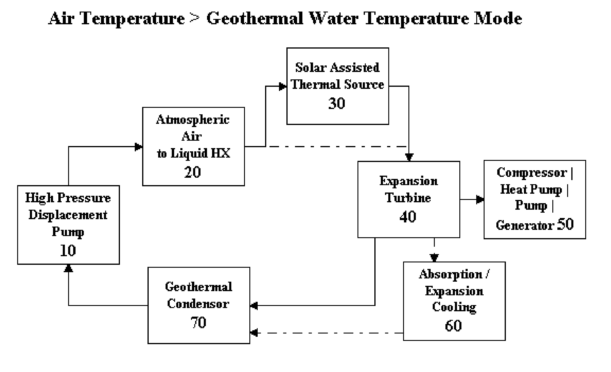
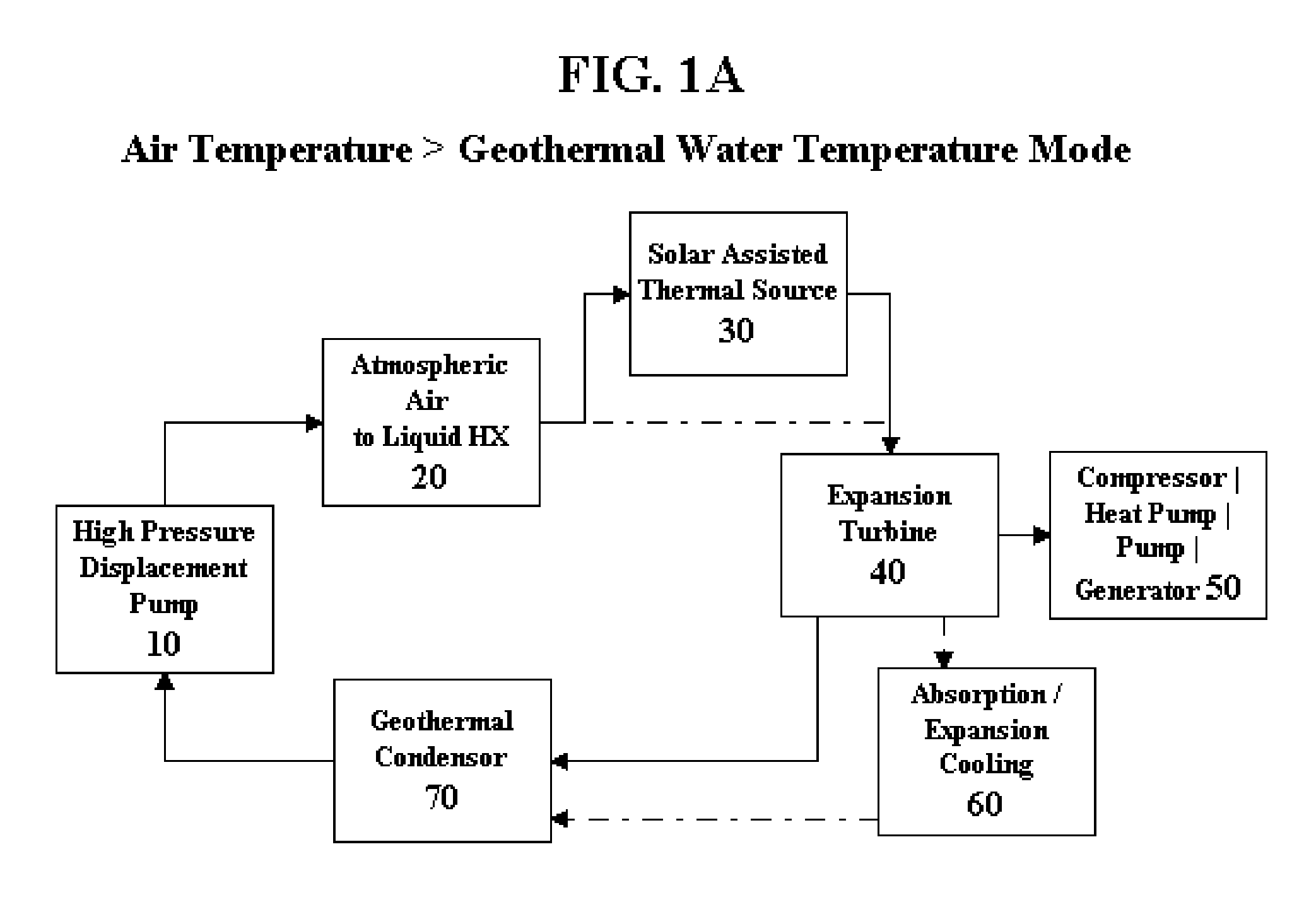
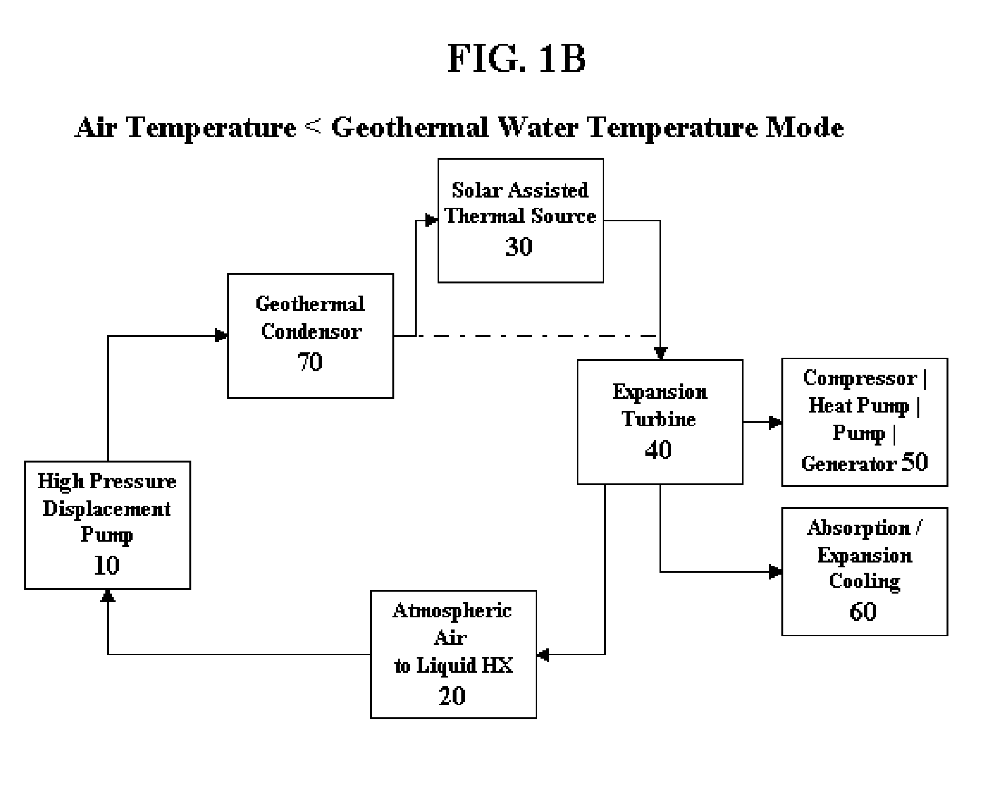
[0041]FIGS. 1A and 1B, which is a block diagram of the fluid communication lines between the power conversion device's major components, depicts numerous inventive features. The thermodynamic power conversion device is a hybrid geothermal thermodynamic cycle, though significantly lower ground source operating temperatures are anticipated in addition to the traditional operating temperatures, coupled with at least one further thermodynamic cycle selected from the group consisting of absorption, adsorption, and vapor compression heat pump.

[0042]FIG. 1A specifically depicts the thermodynamic power conversion device, hereinafter referred to as “TPC”, shows the configuration when the ambient / atmospheric air temperature is greater than the ground source / geothermal water temperature. The ground source water thermal energy is transported...


PUM


Abstract

A high efficiency thermodynamic power conversion cycle is disclosed using thermal storage, atmospheric heat exchangers, and wind channeling in a synergistic method. Using the preferred configuration with ground source water, solar collectors, and heat pump including the further preferred utilization of ionic liquids or electride solutions as the working fluid in the system, achieves optimal total energy efficiency and enables otherwise insufficient thermal differentials to effectively generate power.

Description

CROSS-REFERENCE TO RELATED APPLICATIONS [0001] This application claims priority from U.S. Provisional Patent Application Ser. No. 60 / 766,013 filed Dec. 29, 2005 and titled “Thermodynamic Power Conversion Cycle and Methods of Use” and is a continuation-in-part of U.S. Patent Application Ser. No. 60 / 595,167 filed Jun. 13, 2005, having the title “Nano-Ionic Liquids and Methods of Use” and included as reference only without priority claims and a continuation-in-part of U.S. Patent Application Ser. No. 60 / 593,485 filed Jan. 18, 2005, having the title “High Efficiency Absorption Heat Pump and Methods of Use” and included as reference only without priority claims.FIELD OF THE INVENTION [0002] The invention is directed generally to power generation cycles based on thermodynamic cycles, and more specifically to means and methods to increase the effective thermal differential between the heat source and sink, and means and methods to increase the pressure differential across the power extract...

Claims


Application Information

Patent Timeline
Patent Type & Authority Applications(United States)
IPC IPC(8): F03G7/00F03G6/00F01K27/00B60L8/00B60K16/00
CPCF01K3/12F01K25/08F03G6/003Y02E10/46F03G7/04Y02E10/34F03G6/065Y02E10/30Y02T10/7072F03G7/047
Inventor GURIN, MICHAEL H.
Owner ECHOGEN POWER SYST
Why Eureka
Try Eureka