Highly efficient counter electrode for dye-sensitized solar cell and method of producing the same

Inactive Publication Date: 2006-04-06
KOREA INST OF SCI & TECH
View PDF8 Cites 46 Cited by
  • Summary
  • Abstract
  • Description
  • Claims
  • Application Information

AI Technical Summary

Benefits of technology

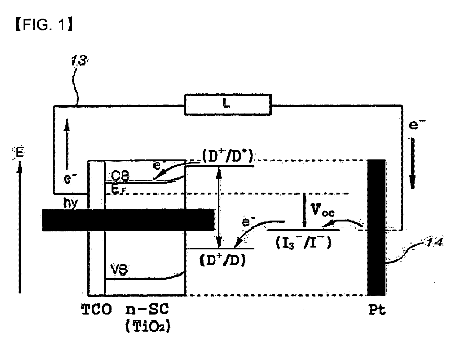
[0029] In the counter electrode for the dye-sensitized solar cell according to the present invention, an electron transfer layer, which is capable of promoting smooth electron transfer through an interface between an electrolyte and the counter electrode, is laminated, and a specific surfac

Problems solved by technology

However, it is problematic in that it is difficult to produce a solar cell having high energy conversion efficiency.
However, the dye-sensitized solar cell employing the liquid electrolyte is disadvantageous in that light conversion efficiency is less than about 8-9% (@ 100 mW/cm2) which is lower than tha

Method used

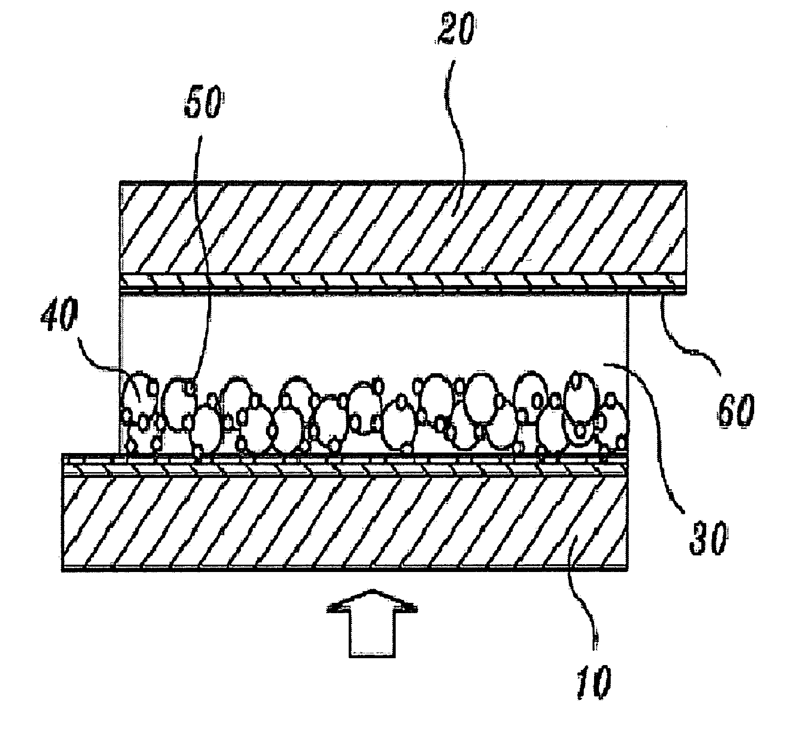
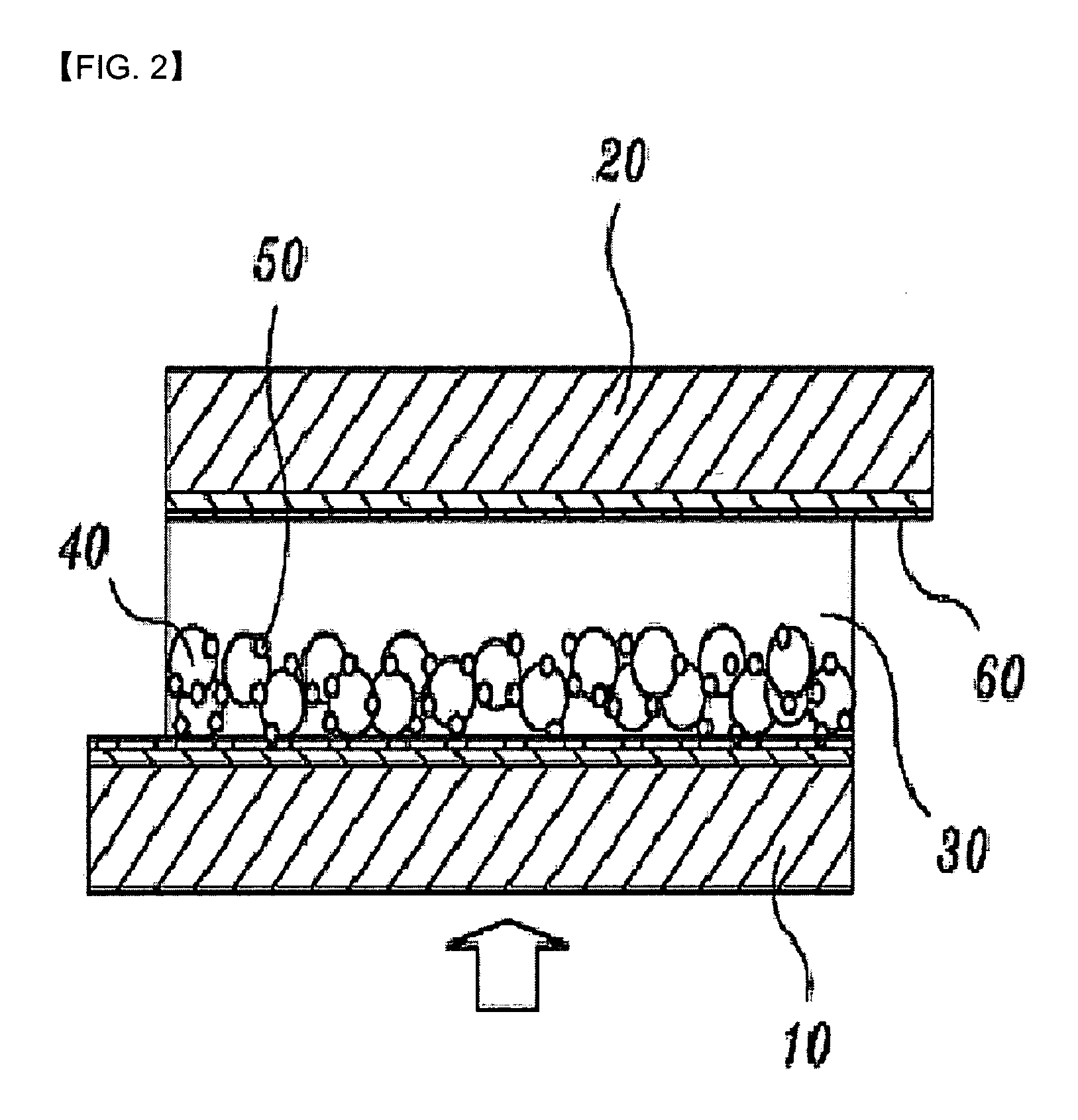

Image

  • Highly efficient counter electrode for dye-sensitized solar cell and method of producing the same
  • Highly efficient counter electrode for dye-sensitized solar cell and method of producing the same
  • Highly efficient counter electrode for dye-sensitized solar cell and method of producing the same

Examples


example 1

[0094] Production of a Counter Electrode, in which a Conductive Polymer is Applied on the Counter Electrode, Coated with a Base Platinum Layer, to Form an Electron Transfer Layer

[0095] After the predetermined amount of H2PtCl6 solution (0.05 M in isopropanol) was dropped on a conductive substrate, the resulting substrate was subjected to a spin coating process (1st: 1000 rpm, 10 sec; and 2nd: 2000 rpm, 40 sec), heated from room temperature to 450° C. for 2 hours, heat treated at 450° C. for 20 min, and cooled to room temperature for 8 hours. Thereby, the application of a base platinum layer on the conductive substrate was completed. Hereinafter, a procedure of applying the base platinum layer on the conductive substrate will be conducted in the same manner. After the predetermined amount of conductive polymer solution dissolved in an organic solvent was dropped on a counter electrode, on which the base platinum layer is applied, a spin coating process (1st: 1000 rpm, 10 sec; and 2n...

example 2

[0096] Production of a Counter Electrode, in which Platinum Nanoparticles are Electrochemically Applied on the Counter Electrode, Coated with a Base Platinum Layer, to Form an Electron Transfer Layer

[0097] The two counter electrodes coated with the base platinum layer were positioned in an electrophoretic cell. In this regard, a distance between the two electrodes was maintained at 1 mm. The predetermined amount of platinum nanoparticles having a particle size of about 500 nm or less was put into a mixed solution of acetone / ethanol (1 / 1, v / v), and subjected to an ultrasonic treatment to be completely dispersed. A predetermined voltage was applied while the counter electrodes were completely dipped in the platinum nanoparticle solution, thereby inducing electrophoresis of the platinum particles. After the platinum nanoparticles were applied on the counter electrodes, they were heat treated (at 450° C. for 20 min) to improve the contact between the platinum nanoparticles.

example 3

[0098] Production of a Counter Electrode, in which a Platinum Nanoparticle Layer is Electrochemically Applied on the Counter Electrode, Coated with a Base Platinum Layer, and a Conductive Polymer Layer is then Laminated on the Resulting Counter Electrode to Form an Electron Transfer Layer

[0099] A counter electrode, on which platinum nanoparticles were applied, was produced according to the same procedure as in example 2, and a conductive polymer was applied on the resulting counter electrode using a spin coating process and then subjected to a doping process according to the same procedure as example 1.


PUM

PropertyMeasurementUnit
Particle sizeaaaaaaaaaa
Flexibilityaaaaaaaaaa
Ratioaaaaaaaaaa

Abstract

Disclosed herein is a counter electrode for a dye-sensitized solar cell, and a method of producing the same. In the dye-sensitized solar cell which includes a photoelectrode containing a photosensitive dye molecules, in which the counter electrode is positioned opposite to the photoelectrode, and an electrolytic solution interposed between the photoelectrode and the counter electrode, the counter electrode has an electron transfer layer. The electron transfer layer has a structure in which one or more conductive materials, selected from the group consisting of a conductive polymer, platinum nanoparticles, a carbon compound, inorganic oxide particles, and a conductive polymer blend, are sequentially laminated. In the counter electrode, the electron transfer layer promotes smooth electron transfer through an interface between the electrolyte, containing pairs of redox ions, and counter electrode. Thereby, energy conversion efficiency is significantly improved in comparison with a conventional dye-sensitized solar cell employing a counter electrode in which only a platinum layer is applied on a transparent conductive material.

Description

BACKGROUND OF THE INVENTION [0001] 1. Field of the Invention [0002] The present invention relates to a counter electrode for a dye-sensitized solar cell and a method of producing the same. More particularly, the present invention pertains to a counter electrode for a dye-sensitized solar cell which includes a photoelectrode containing a photosensitive dye molecules, in which the counter electrode is positioned opposite to the photoelectrode, and an electrolytic solution interposed between the photoelectrode and the counter electrode, and a method of producing the same. At this time, the counter electrode has an electron transfer layer. The electron transfer layer has a structure in which one or more conductive materials, selected from the group consisting of a conductive polymer, platinum nanoparticles or a thin platinum film, a carbon compound, inorganic oxide particles, and a conductive polymer blend, are sequentially laminated. [0003] 2. Description of the Related Art [0004] A re...

Claims


Application Information

Patent Timeline
IPC IPC(8): H01L31/00
CPCH01G9/2022H01G9/2031Y10T436/147777Y02E10/542H01L51/0038Y02P70/50H10K85/114H01L31/04H01L31/0224H01L31/18
Inventor KANG, YONG SOOJUNG, BUM SUKKIM, YOUNG JINKANG, MOON SUNG
Owner KOREA INST OF SCI & TECH
Why Eureka
Try Eureka