TCO-based hybrid solar photovoltaic energy conversion apparatus

a solar photovoltaic energy and hybrid technology, applied in the direction of electrical equipment, basic electric elements, semiconductor devices, etc., can solve the problems of low ineffective enhancement of solar photovoltaic energy conversion efficiency, and only absorbing sunlight within the visible light wavelength range of solar cells made of the above-mentioned materials, etc., to achieve high visible light transparency, low cost, and high coating capability

Inactive Publication Date: 2009-04-02
CHANG GUNG UNIVERSITY
View PDF6 Cites 47 Cited by
  • Summary
  • Abstract
  • Description
  • Claims
  • Application Information

AI Technical Summary

Benefits of technology

[0020]The invention utilizes the advantages of the transparent conductive oxide such as low cost, high visible light transparency, and large area coating capability to increase total power generation output by increasing the absorbing area.
[0021]The invention combines high solar photovoltaic energy conversion efficiency of opaque solar cells and high visible light transparency of the transparent conductive oxide to form a solar photovoltaic energy conversion apparatus with high visible light transparency and high photovoltaic energy conversion efficiency.

Problems solved by technology

In addition, due to the optoelectronic characteristics of materials, solar cells made by the above-mentioned materials can only absorb sunlight within the wavelength range of the visible light.
Thus, the solar photovoltaic energy conversion efficiency is unable to be enhanced effectively.
Therefore, how to integrate the advantages of both kinds of solar cells has become an important research and development issue for the next generation solar cells.
Though multi-layers of transparent conductive oxide thin films are used, it is still the transparent solar cell with low solar photovoltaic energy conversion efficiency.
In addition to higher manufacturing cost, only opaque solar cell with no visible light transparency is formed.

Method used


Image

  • TCO-based hybrid solar photovoltaic energy conversion apparatus
  • TCO-based hybrid solar photovoltaic energy conversion apparatus
  • TCO-based hybrid solar photovoltaic energy conversion apparatus

Examples


Embodiment Construction

[0026]The following is a description of the present invention. The invention firstly will be described with reference to one exemplary structure. Some variations will then be described as well as advantages of the present invention. A preferred method of fabrication will then be discussed. An alternate, asymmetric embodiment will then be described along with the variations in the process flow to fabricate this embodiment.

[0027]The invention relates to a solar photovoltaic energy conversion apparatus, more particularly to a transparent conductive oxide (TCO) based hybrid solar cell device, which not only allows the transmission of visible sunlight but also can enhance the photovoltaic energy conversion efficiency. The transparent conductive oxide material is adopted in the structure. The following detailed description is included in the structure of the solar cell:

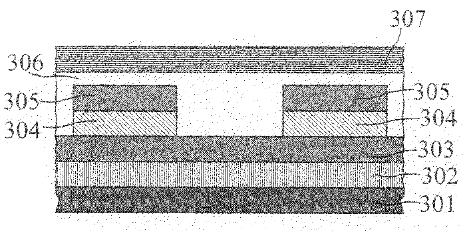
[0028]As shown in FIG. 3, there is a substrate 301 in the structure, which is normally made of glass, quartz or mono-crys...


PUM


Abstract

The invention relates to a solar photovoltaic energy conversion apparatus. The apparatus consists of a substrate, a buffer layer formed on the substrate layer, a first transparent conductive oxide layer formed on the buffer layer, periodic protrusions containing first silicon layers formed on the first transparent conductive oxide layer, second silicon layers formed on the first silicon layers, a second transparent conductive oxide layer covering the first silicon layers, the second silicon layers and the first transparent conductive oxide layer, and an anti-reflective protective layer. The first silicon layer and the second silicon layer are the electrodes with the opposite type of charge carriers. The first transparent conductive layer and the second transparent conductive layer are the electrodes with the opposite type of charge carriers. This TCO-based hybrid solar photovoltaic energy conversion device not only can allow the transmission of visible sunlight but also can enhance the photovoltaic energy.

Description

BACKGROUND OF THE INVENTION[0001]1. Field of the Invention[0002]The invention relates to a solar photovoltaic energy conversion apparatus, more particularly to a transparent conductive oxide (TCO) based hybrid solar cell device, which not only allows the transmission of visible sunlight but also can enhance the photovoltaic energy conversion efficiency.[0003]2. Description of the Prior Art[0004]The earliest development of the solar cell system can be traced back to 1954, which was invented and proposed by Bell Laboratory in the United States. Solar cell is a kind of solar photovoltaic energy conversion semiconductor devices that uses sunlight to generate electric power directly. By adding impurity substances into highly pure semiconductor materials, semiconductors with different property can be made. For example, boron can be added into silicon to form p-type semiconductor while phosphorus can be added into silicon to form n-type semiconductor. When p-type and n-type semiconductors ...

Claims


Application Information

Patent Timeline
Patent Type & Authority Applications(United States)
IPC IPC(8): H01L31/00
CPCH01L31/02168Y02E10/50H01L31/0236H01L31/022466H01L31/02363
Inventor LU, HSIN-CHUNWU, KUO-MEICHANG, PEN-HSIUCHU, CHUN-LUNGLAI, CHI-YO
Owner CHANG GUNG UNIVERSITY
Why Eureka
Try Eureka