Photo-luminescence color liquid crystal display

a liquid crystal display and photoluminescence technology, applied in the field of color displays, can solve the problems of wasting significant amount of backlight intensity, complicated driving circuitry, and unfavorable backlight intensity control, and achieve the effect of improving contrast ratio, purity and realism, and achieving 90 percent efficiency of light outpu

Inactive Publication Date: 2008-03-27
INTEMATIX
View PDF100 Cites 46 Cited by
  • Summary
  • Abstract
  • Description
  • Claims
  • Application Information

AI Technical Summary

Benefits of technology

[0034] The current LCD technology that employs color filters has only about a 10 to 20 percent efficiency of light output that is achievable at the front of a liquid crystal display. By contrast, the present embodiments using a phosphor-based color rendering scheme, including using red-green phosphor elements plus blue LED illumination, can have up to 90 percent efficiency of light output. With a broader color range, phosphors and LED backlight together render truer skin tones and vivid reds and greens, offering better contrast ratios, purity and realism, and meeting new consumer expectations.

Problems solved by technology

This approach unfortunately requires complex driving circuitry to properly control the intensities of the three different color LEDs since different circuitry is necessary because each of the LEDs demands different drive conditions.
Unfortunately the white light product of such LEDs does not match well with the color filters used in current LCDs, and a significant amount of the backlight intensity is wasted.

Method used


Image

  • Photo-luminescence color liquid crystal display
  • Photo-luminescence color liquid crystal display
  • Photo-luminescence color liquid crystal display

Examples


Embodiment Construction

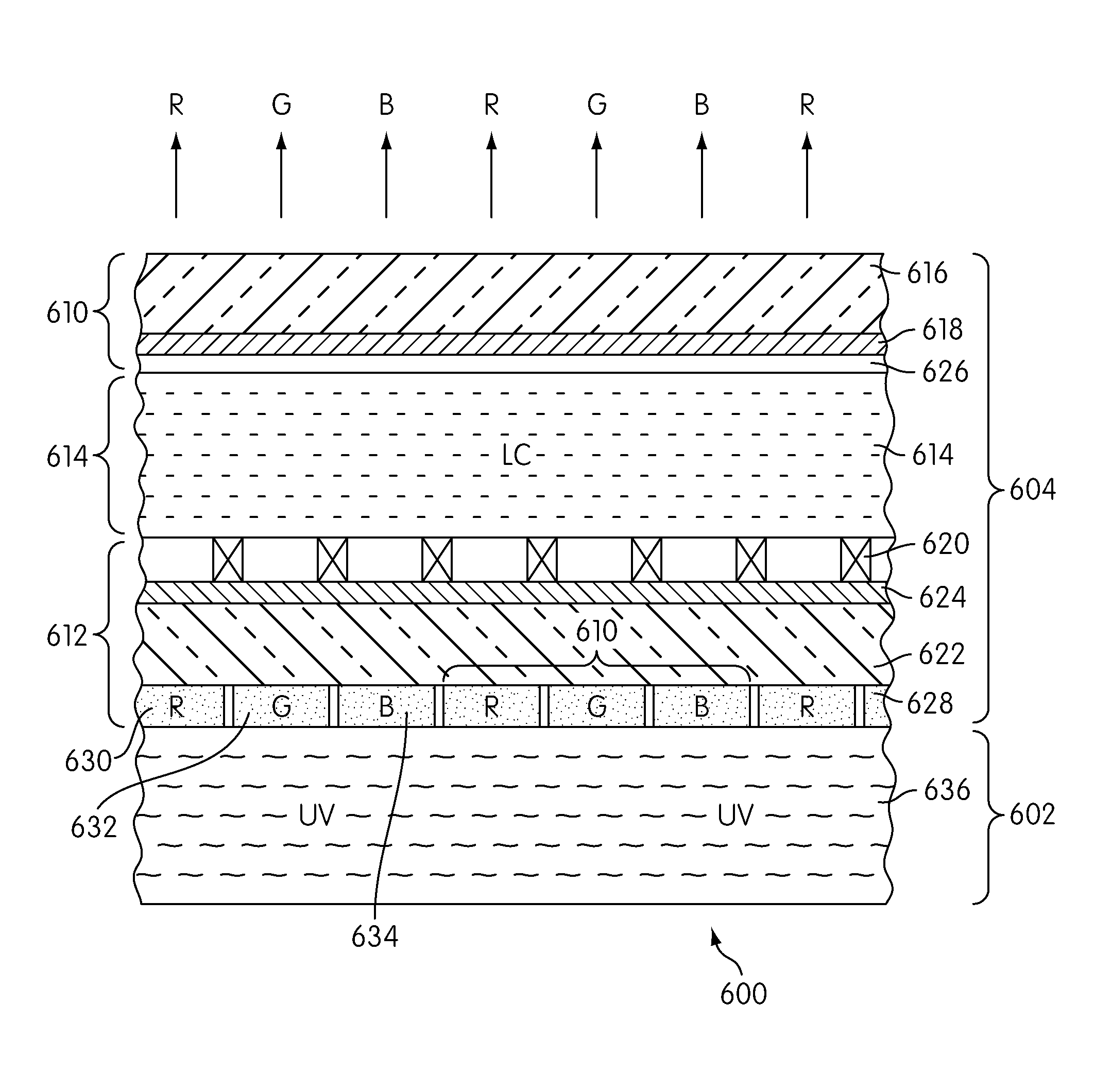
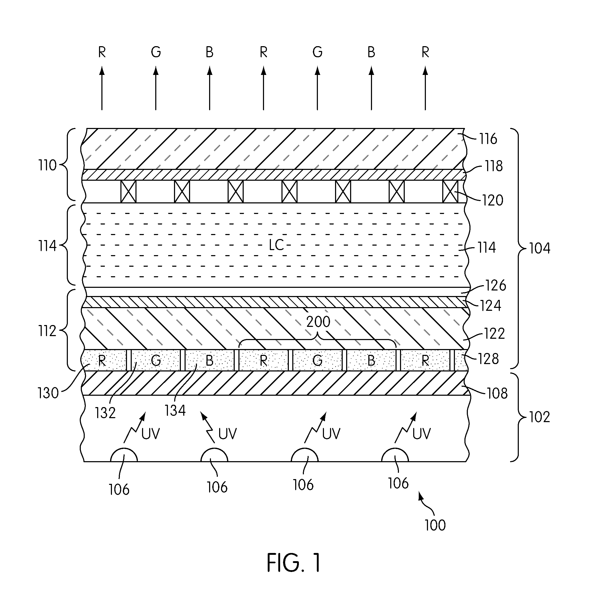
[0043] Disclosed herein is a novel color rendering scheme designed to improve and enhance the brightness and sharpness of an electronic display, such as a liquid crystal display (LCD). Embodiments of the present invention incorporate two key components: 1) a red-green (RG) or red-green-blue (RGB) phosphor panel, and 2) a monochromatic or quasi-monochromatic short-wavelength light source for exciting the RGB phosphors of the RG phosphor panel. These components replace the color-filter panel and the broadband white light source, respectively, which have been traditionally used in prior art LCDs.

[0044] Referring to FIG. 1 there is shown a schematic cross-sectional representation of a photo-luminescence color LCD 100 according to a first embodiment of the invention. The LCD 100 comprises a display panel 102 and a backlighting unit 104.

[0045] The backlighting unit 104 comprises either a single excitation radiation source or a plurality of sources 106 and a light diffusing plane 108. Ea...


PUM

PropertyMeasurementUnit
wavelengthaaaaaaaaaa

Abstract

A photo-luminescence liquid crystal (LCD) display comprises: a display panel and a radiation source for generating excitation radiation for operating the display. The display panel comprises transparent front and back plates; a liquid crystal disposed between the front and back plates; a matrix of electrodes (array of thin film transistors TFTs) defining red, green and blue pixel areas of the display and operable to selectively induce an electric field across the liquid crystal in the pixel areas for controlling transmission of light through the pixels areas. A red phosphor material which emits red (R) light in response to excitation radiation is provided on the back plate corresponding to red pixel areas and a green phosphor material which emits green light in response to excitation radiation is provided on the back plate corresponding to green pixel areas.

Description

CROSS REFERENCE TO RELATED APPLICATION [0001] This application claims the benefit of priority to U.S. Provisional Application No. 60 / 819,420 filed Jul. 6, 2006, the specification and drawings of which are incorporated herein by reference.BACKGROUND OF THE INVENTION [0002] 1. Field of the Invention [0003] The present invention relates to the field of color displays, such as flat panel displays and color liquid crystal displays (LCDs), which convert electrical signals into color images. In particular, the invention concerns color, transmissive LCDs in which phosphor, photo-luminescent, materials are used to generate color light in response to excitation radiation from a backlight, such displays being termed photo-luminescence color LCDs or photo-luminescent color LCDs. [0004] 2. Description of the Related Art [0005] The light that lights up our world and allows us to see comes from solar energy in what is known as the visible region of the solar, electromagnetic, spectrum. This region...

Claims


Application Information

Patent Timeline
Patent Type & Authority Applications(United States)
IPC IPC(8): G02F1/13357H01L33/50
CPCG02F1/133617G02F1/133512G02F2203/34G02F2001/133567G02F1/133567G02F1/1335
Inventor LI, YI-QUNDONG, YISHAN, WEI
Owner INTEMATIX
Why Eureka
Try Eureka