Heat flux sensor and preparation method thereof

A technology of heat flow sensor and thermal resistance layer, which is applied in the field of heat flow sensor and its preparation, can solve the problems of difficult design of thin-film thermocouples, easy introduction of errors, complicated process, etc., and achieve the effects of facilitating measurement, reducing interference, and reducing overall size

Inactive Publication Date: 2019-08-16
48TH RES INST OF CHINA ELECTRONICS TECH GROUP CORP
View PDF7 Cites 4 Cited by
  • Summary
  • Abstract
  • Description
  • Claims
  • Application Information

AI Technical Summary

Problems solved by technology

The more conventional method is to make leads on the substrate by smearing silver paste or pre-embedding metal wires on the appropriate position of the substrate surface. This process is complicated and easy to introduce errors, and it is easy to cause the risk of falling off and failure under high temperature environment.
Therefore, the existing MEMS process heat flow sensor, the signal extraction of the thin film thermocouple at a higher temperature has always been a difficult point in the design

Method used


Image

  • Heat flux sensor and preparation method thereof
  • Heat flux sensor and preparation method thereof
  • Heat flux sensor and preparation method thereof

Examples


Embodiment Construction

[0029] The present invention will be further described below in conjunction with the accompanying drawings and specific embodiments.

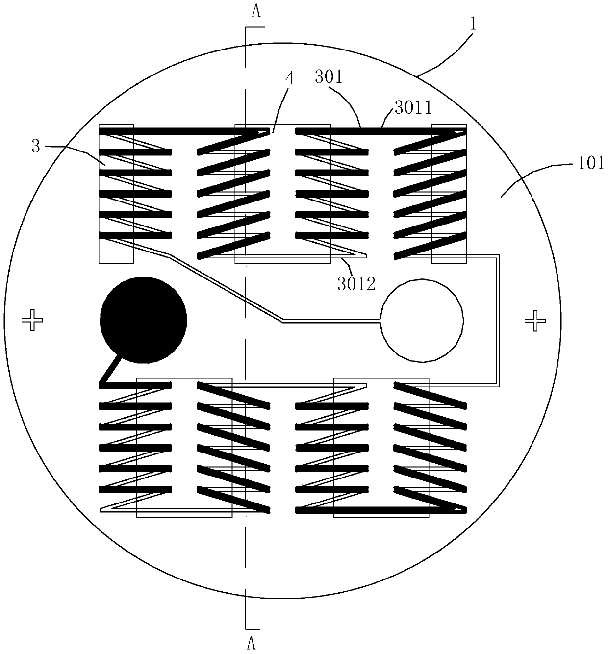
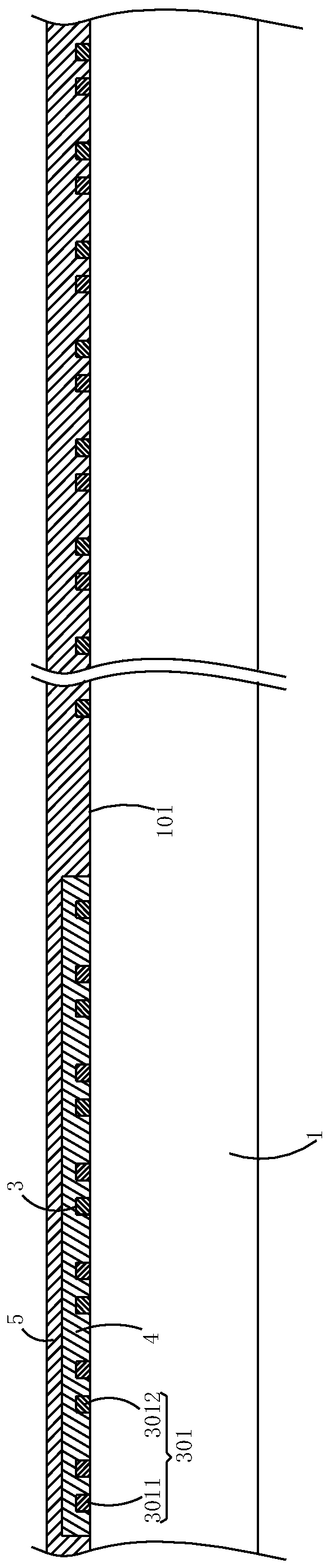
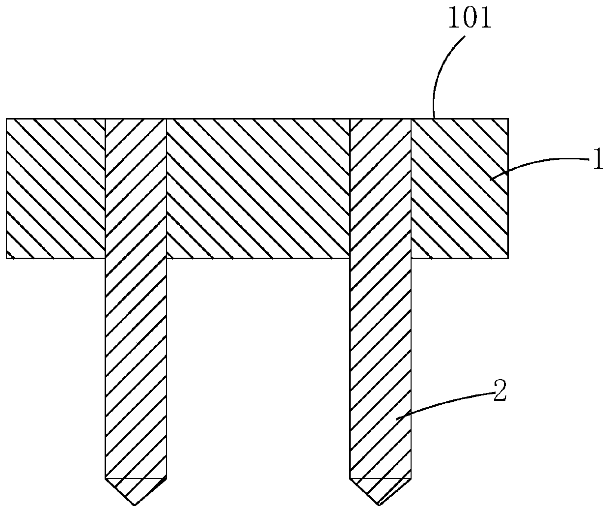
[0030] Such as figure 1 As shown, the heat flow sensor of this embodiment is suitable for the test environment of a pulsed hypersonic wind tunnel, and includes an electrode 2 and a probe 1 with electrical insulation properties. The probe 1 and the electrode 2 are integrally sintered; the electrode 2 One end of the probe 1 is embedded into the probe 1 and one end is flush with the measuring surface 101 of the probe 1. The side of the probe 1 that is flush with the electrode 2 is the measuring surface 101; directly deposited on the measuring surface 101 of the probe 1 is Thermopile 3, the two ends of thermopile 3 (as figure 1 shown by the two circles in ) are respectively deposited on the end faces of the electrodes 2; the thermopile 3 includes a plurality of thermocouple units 301 connected in series in sequence, and the thermocouple units 301 ...


PUM

PropertyMeasurementUnit
thicknessaaaaaaaaaa
thicknessaaaaaaaaaa

Abstract

The invention discloses a heat flux sensor. The heat flux sensor comprises electrodes and a measuring head, wherein the electrodes and the measuring head are integrally sintered, a thermopile is directly deposited on a measuring face of the measuring head, and the two ends of the thermopile are deposited on end faces of the electrodes respectively; the thermopile comprises multiple thermocouple units connected in series, and each thermocouple unit comprises a cold node and a hot node which are connected with each other; a thermal resistance layer is deposited on the measuring face; one part ofeach cold node and one part of each hot node are both arranged between the thermal resistance layer and the measuring face; and protective films are deposited on the thermopile and the thermal resistance layer respectively. The heat flux sensor has the advantages of being high in response speed, high in sensitivity, simple in structure and the like. The invention further discloses a preparation method. The preparation method comprises the steps that S01, the electrodes, ceramic and glass powder are sintered to prepare an integrated structure; S02, film coating is directly performed on the measuring face through an ion beam sputtering process to form the thermopile and the thermal resistance layer; and S03, the protective films are deposited. The preparation method has the advantages of being simple in process and the like.

Description

technical field [0001] The invention mainly relates to the technical field of heat flow, in particular to a heat flow sensor and a preparation method thereof. Background technique [0002] Heat flow sensor, used to measure heat flux density, is an important measurement device for studying heat transfer. Among them, the thermal resistance heat flow sensor, as the commonly used sensor at present, uses the measurement principle of the thermopile to measure the heat flow. The temperature difference between the upper and lower surfaces of the thermal resistance layer of the thermal resistance heat flow sensor is proportional to the input current, but the temperature difference characteristic that the heat flow is proportional to the size is only established when the heat flow change is lower than a certain frequency. Since the thermal resistance layer needs time to reach a thermally stable state, this time (or frequency threshold) limits the frequency of heat flow changes, and t...

Claims


Application Information

Patent Timeline
Patent Type & Authority Applications(China)
IPC IPC(8): G01K17/00G01K17/16
CPCG01K17/00G01K17/16
Inventor 丁玎何峰周国方张浩
Owner 48TH RES INST OF CHINA ELECTRONICS TECH GROUP CORP
Why Eureka
Try Eureka