
Catheter for delivering a tissue ablation probe

a catheter and ablation probe technology, applied in the field of medical devices, can solve the problems of difficult to achieve linear ablation, and difficult to achieve continuous ablation lines in catheter ablation techniques, so as to achieve effective tissue ablation time

Inactive Publication Date: 2008-08-26
A F M MEDICAL SYST
View PDF10 Cites 11 Cited by
  • Summary
  • Abstract
  • Description
  • Claims
  • Application Information

AI Technical Summary

Problems solved by technology

However, ablation of cardiac tissue along a continuous trace over a tissue surface (referred to herein as “linear ablation”) is difficult to achieve by this technique.
However, generating continuous ablation lines in catheter ablation techniques is difficult to achieve.
While the open heart procedure is more traumatic and fully invasive, it is none the less become the standard ablation procedure.
The lack of a direct view of these regions by the surgeon during an open heart procedure complicates the open heart ablation procedure.

Method used


Image

  • Catheter for delivering a tissue ablation probe
  • Catheter for delivering a tissue ablation probe
  • Catheter for delivering a tissue ablation probe

Examples


Embodiment Construction

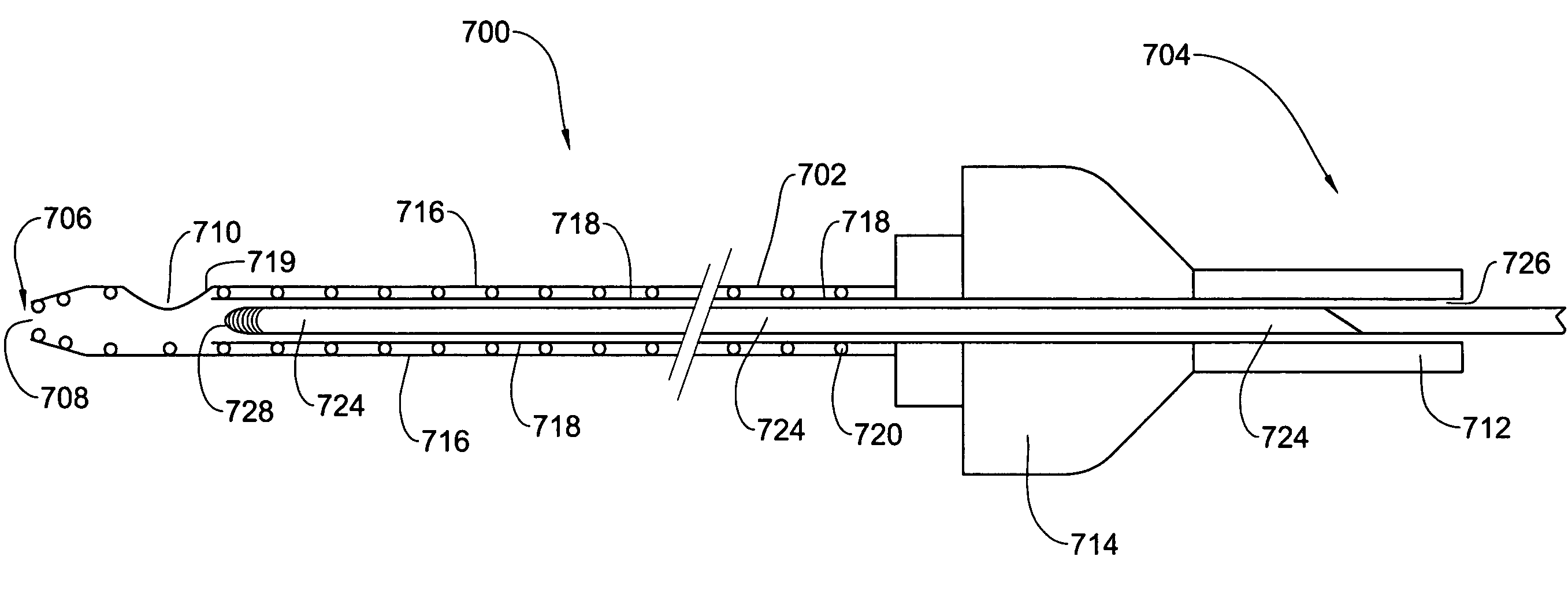
[0042]Referring first to FIG. 7, FIGS. 7a through 7f show a delivery catheter for delivering a tissue ablation probe to a body site, in accordance with one embodiment of the invention. As seen in FIG. 7a, the delivery catheter 700 has a slender flexible shaft 702 having a proximal end 704 and a distal end 706. The distal end 706 is tapered and terminates in a terminal opening 708. A side opening 710 is located in the wall of the shaft 702 near its distal end 706. The proximal end 704 of the catheter 702 has a handle 712 and a controller 714 described in detail below.

[0043]FIG. 7b shows the delivery catheter 700 in longitudinal section. The shaft 702 of the catheter 700 comprises an outer sheath 716. Within the outer sheath 716 is an inner sleeve 718. The inner sleeve 718 extends from an opening 726 in the handle 712 through the handle 712 and controller 714 through the outer sheath 716, and terminates in a distal end 715 just proximally to the side opening 710. A helical spring 720 ...


PUM


Abstract

A delivery catheter having a shaft with a distal end and a proximal end for delivering an ablation probe to a body site. The delivery catheter comprises mounting members located at the distal end configured to receive an ablation probe; and attachment members configured to attach the distal end to a tissue surface. The delivery catheter preferably configured to allow an ablation probe mounted on the distal end to be manipulated so as to extend from the distal end in a direction selected from a range of directions. Even more preferably, the delivery catheter is configured to allow an ablation probe mounted on the distal end to be manipulated so as to move along a tissue surface and perform linear ablation. The invention also provides a system comprising the delivery catheter of the invention and an ablation device having an ablation probe, wherein the delivery catheter and the ablation probe are configured to allow the ablation probe to be mounted at the distal end of the delivery catheter.

Description

[0001]This application claims the benefit of prior U.S. provisional patent application No. 60 / 490,263 filed Jul. 28, 2003, the contents of which are hereby incorporated by reference in their entirety.FIELD OF THE INVENTION[0002]The present invention is generally in the field of medical devices. More specifically, the invention concerns delivery catheters for delivering an object to a body site.BACKGROUND OF THE INVENTION[0003]Medical refractory cardiac arrhythmia can be treated using catheter ablation techniques. However, ablation of cardiac tissue along a continuous trace over a tissue surface (referred to herein as “linear ablation”) is difficult to achieve by this technique. Linear ablation in cardiac tissue is an accepted procedure for treating arrhythmias, such as atrial fibrillation, which is the most common cardiac arrhythmia. In this procedure, more than one line of tissue ablation is usually needed for successful treatment. However, generating continuous ablation lines in c...

Claims


Application Information

Patent Timeline
Patent Type & Authority Patents(United States)
IPC IPC(8): A61B18/18A61B18/02A61B18/14A61B18/24
CPCA61B18/1492A61B18/02A61B18/18A61B18/24A61B2018/1435A61B2018/00291A61B2018/00351A61B2018/1425A61B2018/00273
Inventor AD, NIV
Owner A F M MEDICAL SYST
Learn More