Eureka AIR delivers breakthrough ideas for toughest innovation challenges, trusted by R&D personnel around the world.

Fiber bed assembly and fiber bed therefor

a fiber bed and fiber bed technology, applied in the direction of auxillary pretreatment, separation process, filtration separation, etc., can solve the problems of downstream process equipment corroded, product purity degradation, and ductwork corrosion

Active Publication Date: 2008-08-26
MECS
View PDF66 Cites 18 Cited by
  • Summary
  • Abstract
  • Description
  • Claims
  • Application Information

AI Technical Summary

Problems solved by technology

Re-entrainment of collected liquid from the downstream surface of the fiber bed often causes problems.
These problems can include any of the following individually or in combination; fouling of downstream process equipment, degradation of product purity, corrosion to ductwork and in some cases difficulty in achieving emission requirements.
This problem is particularly severe at the bottom of a vertically disposed fiber bed since all of the liquid collected by the fiber bed necessarily drains to the bottom and from a practical standpoint because of gas phase drag on the liquid, out the downstream surface at the bottom of the fiber bed.
At this disengagement point where the greatest cumulative drainage occurs, gas phase drag can cause bubbling, “spitting”, jetting or fragmentation of the draining liquid.
In addition, it is difficult to maintain the necessary gas seal between the fiber bed sections and the metal plate to avoid gas bypassing between the section and the adjoining plate.

Method used


Image

  • Fiber bed assembly and fiber bed therefor
  • Fiber bed assembly and fiber bed therefor
  • Fiber bed assembly and fiber bed therefor

Examples


Embodiment Construction

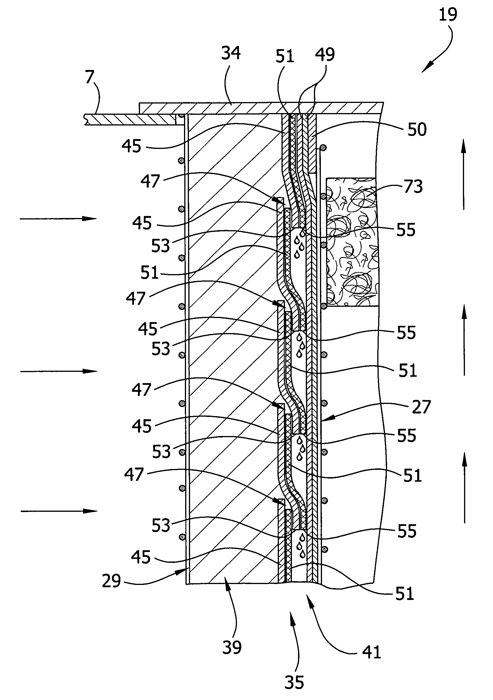
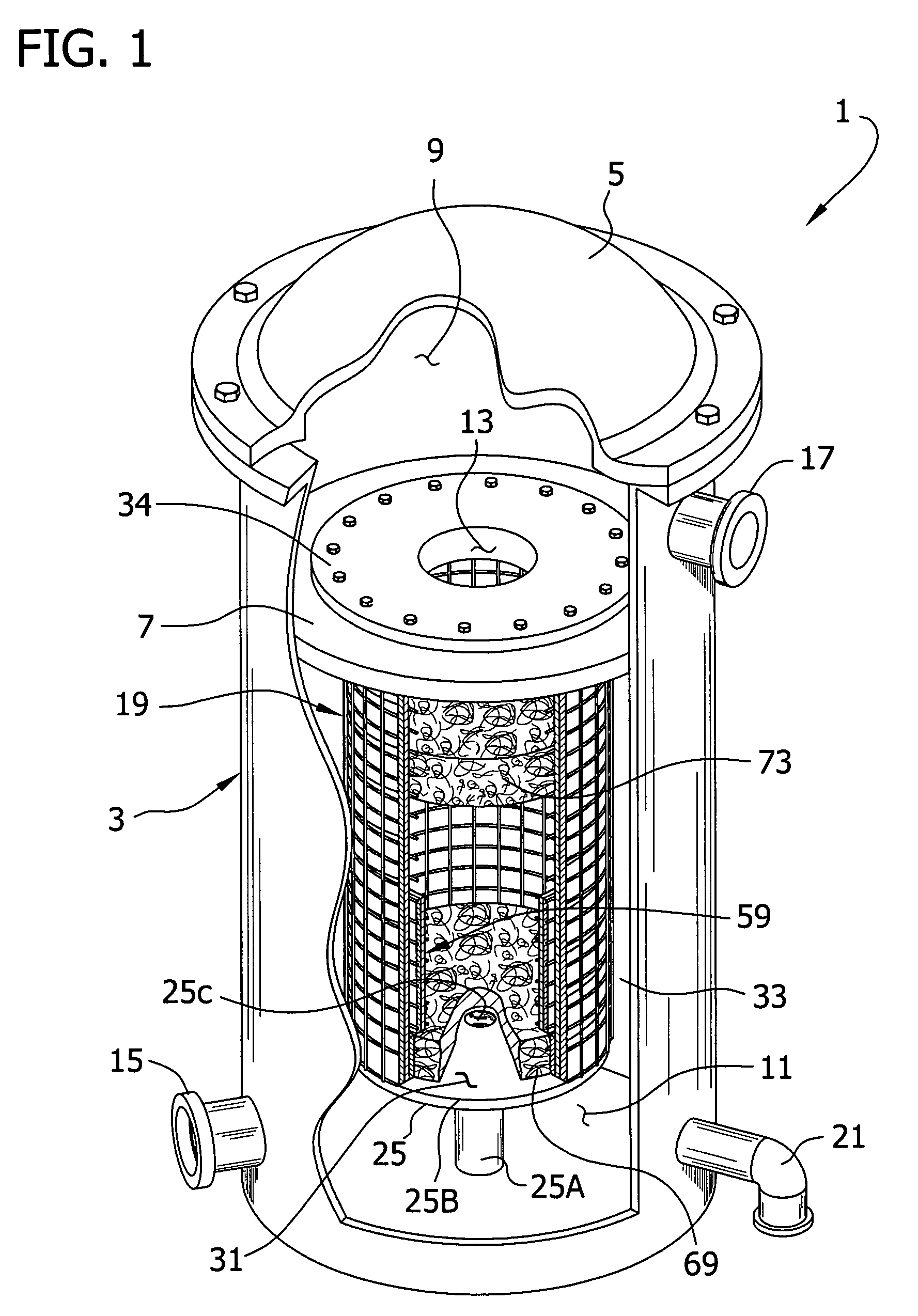
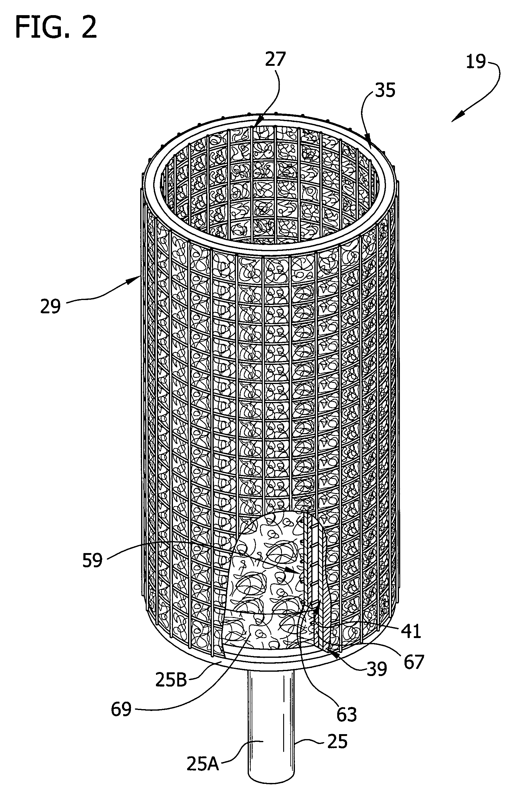
[0017]Referring now to the drawings and in particular to FIG. 1, a mist eliminator (indicated generally at 1) can be placed in the flow line of a stream of gas to remove aerosols and / or wetted soluble solids from the stream of gas. The mist eliminator is of the type that has particular application for use in gas streams having a liquid aerosol content (especially, but not limited to, where there are liquid aerosol particles having submicron sizes) to be removed from the gas stream. The mist eliminator 1 includes a tank (generally indicated at 3) having a removable lid 5 sealingly attached to the tank to close an open top of the tank. An annular mounting plate 7 within the tank 3 divides the tank into an upper chamber 9 and a lower chamber 11. The gas stream may pass from the lower chamber 11 to the upper chamber 9 only through a center hole 13 of the annular mounting plate 7. The tank 3 includes a gas stream inlet 15 for receiving a stream of gas ladened with aerosol and / or wetted s...


PUM

PropertyMeasurementUnit
mean diameteraaaaaaaaaa

Abstract

A fiber bed assembly for a mist eliminator that operates at high efficiency and inhibits re-entrained liquid from leaving the mist eliminator. The fiber bed assembly has a construction that facilitates rapid drainage of liquid collected by the fiber bed. A pre-filter media can be employed upstream of the primary collection media to remove larger liquid drops. The pre-filter media can be used in unique combination with other features to reduce liquid re-entrainment, and / or allow increased flow capacity.

Description

FIELD OF THE INVENTION[0001]The present invention generally relates to an improved fiber bed assembly for the separation of liquid particulates (with or without solids dissolved or suspended therein) from gas streams. More particularly, it relates to a fiber bed assembly having an improved capability for inhibiting re-entrainment of collected liquid.BACKGROUND OF THE INVENTION[0002]Mist eliminators have found widespread use in applications wherein aerosols, particularly of less than 3 microns, must be separated from a gas or vapor (hereinafter and in the claims collectively referred to as “gas”) stream. These mist eliminators include fiber beds through which the gas stream is passed to achieve separation. Some of the more frequent applications of mist eliminators include removal of acid mists, such as sulfuric acid mist, in acid manufacturing processes, plasticizer mists in, for example, polyvinyl chloride floor or wall covering manufacture, water soluble solid aerosols such as, for...

Claims


Application Information

Patent Timeline
Patent Type & Authority Patents(United States)
IPC IPC(8): B01D46/00B01D50/00
CPCB01D46/0031B01D2275/105B01D46/02B01D46/52
Inventor ZIEBOLD, STEVEN A.AZWELL, DOUGLAS E.MUELLER, FREDERICK L.
Owner MECS
Why Eureka
Eureka Blog
Learn More