
Apparatus and method for high-throughput asynchronous communication

a high-throughput asynchronous and communication technology, applied in the field of communication networks, can solve the problems of slow circuitry, low throughput of this communication network, and increasing delay in data transfer between system components

Active Publication Date: 2008-08-26
ORACLE INT CORP
View PDF4 Cites 26 Cited by
  • Summary
  • Abstract
  • Description
  • Claims
  • Application Information

AI Technical Summary

Benefits of technology

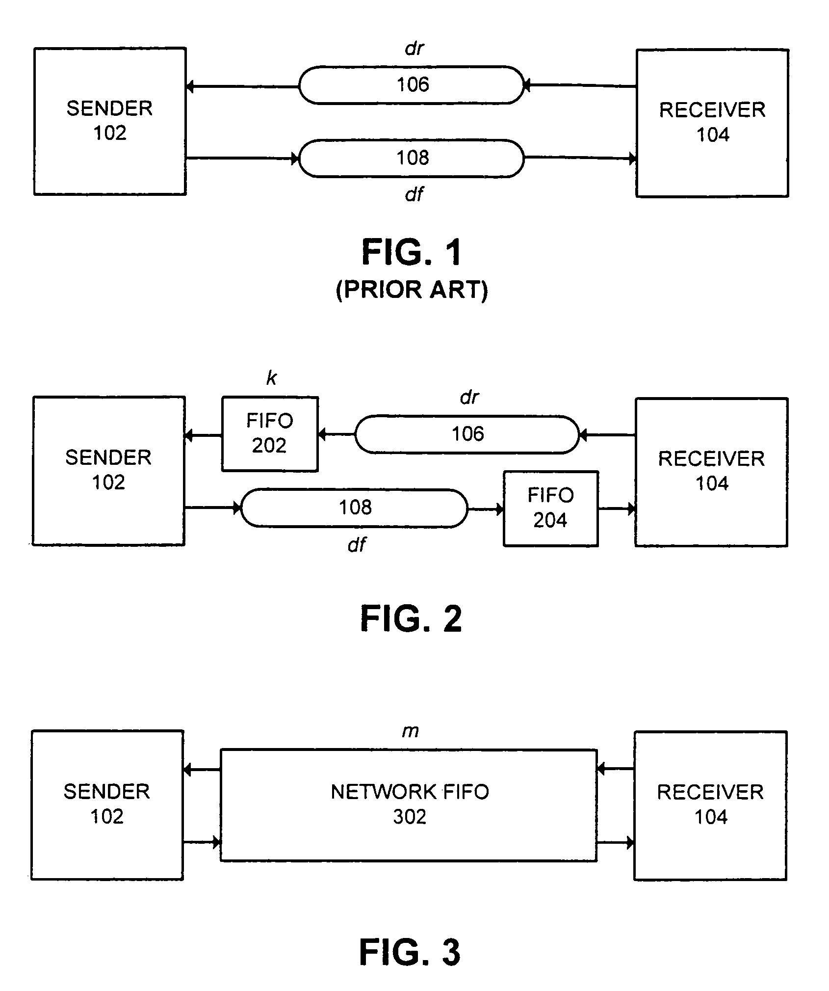
[0011]One embodiment of the present invention provides a system for high-throughput asynchronous communication that includes a sender and a receiver. A sender's first-in, first-out (FIFO) buffer is coupled to an input of the sender, a receiver's FIFO buffer is coupled to an input of the receiver, a forward communication channel is coupled between the sender and the receiver's FIFO buffer, and a reverse communication channel is coupled between the receiver and the sender's FIFO buffer. The forward communication channel, the receiver's FIFO buffer, the reverse communication channel, and the sender's FIFO buffer operate collectively as a network FIFO between the sender and the receiver. The network FIFO is configured to ensure that asynchronous communication between the sender and the receiver takes place reliably and without unnecessary waiting by the sender or the receiver.

Problems solved by technology

While computational circuitry is growing increasingly faster, the delay involved in transferring data between system components is becoming more of a bottleneck.
The problem with the network of FIG. 1 is that the throughput of this communication network is low, because the cycle time is the sum of the large forward and reverse latencies.
However, even when the components are touching each other, the cycles times continue to be very large compared with the cycle times of the individual circuits within the components.

Method used


Image

  • Apparatus and method for high-throughput asynchronous communication
  • Apparatus and method for high-throughput asynchronous communication
  • Apparatus and method for high-throughput asynchronous communication

Examples


an example

[0058]FIG. 8 illustrates an exemplary communication system between a sender and a receiver in accordance with an embodiment of the present invention. Sender 802 is coupled to receiver 808 through forward channel 804 and receiver's FIFO 806. Receiver 808 is coupled to sender 802 through reverse channel 810 and sender's FIFO 812. Sender's FIFO 812 has a capacity of 3 and receiver's FIFO 806 has a capacity of 4. Both FIFOs are initially empty, that is, they include only white tokens. With these values inequalities (1) and (4) are obviously satisfied, because 4=nwsend≦nwrec=5 and 0=nbrec≦nbsend=0, respectively. Provided the other conditions are also satisfied, the composite behaves as a FIFO with capacity nwsend+nbrec=4+0=4.

[0059]The latencies for the FIFOs are as follows. The GasP implementation is a 2-4 GasP implementation, which means that the forward latency per stage is 4 gate delays and the reverse latency per stage is 2 gate delays. Each FIFO has two stages in parallel, the other...


PUM


Abstract

One embodiment of the present invention provides a system for high-throughput asynchronous communication that includes a sender and a receiver. A sender's first-in, first-out (FIFO) buffer is coupled to an input of the sender, a receiver's FIFO buffer is coupled to an input of the receiver, a forward communication channel is coupled between the sender and the receiver's FIFO buffer, and a reverse communication channel is coupled between the receiver and the sender's FIFO buffer. The forward communication channel, the receiver's FIFO buffer, the reverse communication channel, and the sender's FIFO buffer operate collectively as a network FIFO between the sender and the receiver. The network FIFO is configured to ensure that asynchronous communication between the sender and the receiver takes place reliably and without unnecessary waiting by the sender or the receiver.

Description

RELATED APPLICATIONS[0001]This application hereby claims priority under 35 U.S.C. §119 to U.S. Provisional Patent Application No. 60 / 443,592, filed on 29 Jan. 2003, entitled, “High Throughput over High-Latency Asynchronous Communication,” by inventors Josephus C. Ebergen, Ivan E. Sutherland, and Robert J. Drost. Additionally, this application hereby claims priority under 35 U.S.C. §119 to U.S. Provisional Patent Application No. 60 / 508,578, filed on 3 Oct. 2003, entitled, “Maintaining High Throughput FIFO Behavior over High-Latency Communication Channels,” by inventors Josephus C. Ebergen, Ivan E. Sutherland, and Robert J. Drost.GOVERNMENT LICENSE RIGHTS[0002]This invention was made with United States Government support under Contract No. NBCH020055 awarded by the Defense Advanced Research Projects Administration. The United States Government has certain rights in the invention.BACKGROUND[0003]1. Field of the Invention[0004]The present invention relates to communication networks. Mor...

Claims


Application Information

Patent Timeline
IPC IPC(8): H04L12/28H04L12/56H04L1/00
CPCH04L49/901H04L49/90
Inventor EBERGEN, JOSEPHUS C.SUTHERLAND, IVAN E.DROST, ROBERT J.
Owner ORACLE INT CORP
Learn More