
Communication system, master communication device, and slave communication device

a communication system and communication device technology, applied in the direction of digital transmission, data switching network, electrical apparatus, etc., can solve the problems of inability to ensure communication with the rest, inability to transmit or receive data properly,

Inactive Publication Date: 2007-04-19
HITACHI LTD
View PDF6 Cites 58 Cited by
  • Summary
  • Abstract
  • Description
  • Claims
  • Application Information

AI Technical Summary

Benefits of technology

[0007] The technique described in Patent Document 1 has been made with only synchronization in a one-to-one communication in mind; the receiver adjusts its internal clock such that the internal clock is in sync with the clock of the sender based on the time stamp value sent along with the data from the sender. In the case where one communication device communicates with plural communication devices, synchronizing its own internal clock with one of time stamp values sent along with data from the respective communication devices does not ensure communications with the rest of the plural communication devices, unless the sender communication devices are in sync with one another.

Problems solved by technology

In the case where one communication device communicates with plural communication devices, synchronizing its own internal clock with one of time stamp values sent along with data from the respective communication devices does not ensure communications with the rest of the plural communication devices, unless the sender communication devices are in sync with one another.
Furthermore, when the sender communication device is not capable of generating a correct time stamp value due to a failure in the internal clock, the receiver, having no way of knowing the fact, adjusts its internal clock in accordance with an incorrect time stamp value received and thereby makes it impossible to transmit or receive data properly.

Method used


Image

  • Communication system, master communication device, and slave communication device
  • Communication system, master communication device, and slave communication device
  • Communication system, master communication device, and slave communication device

Examples


Embodiment Construction

[0022] The following is a description on an embodiment of the present invention.

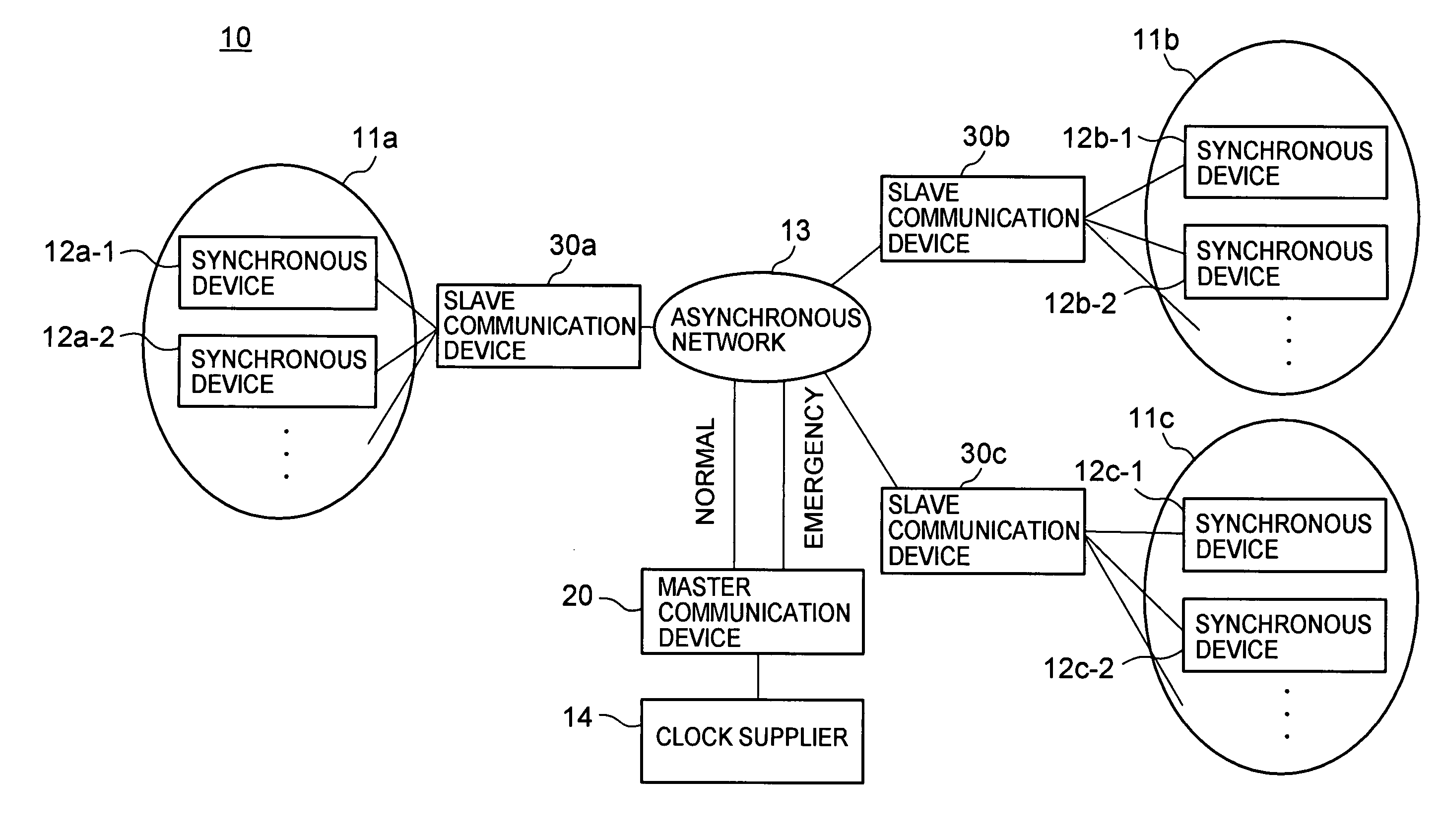
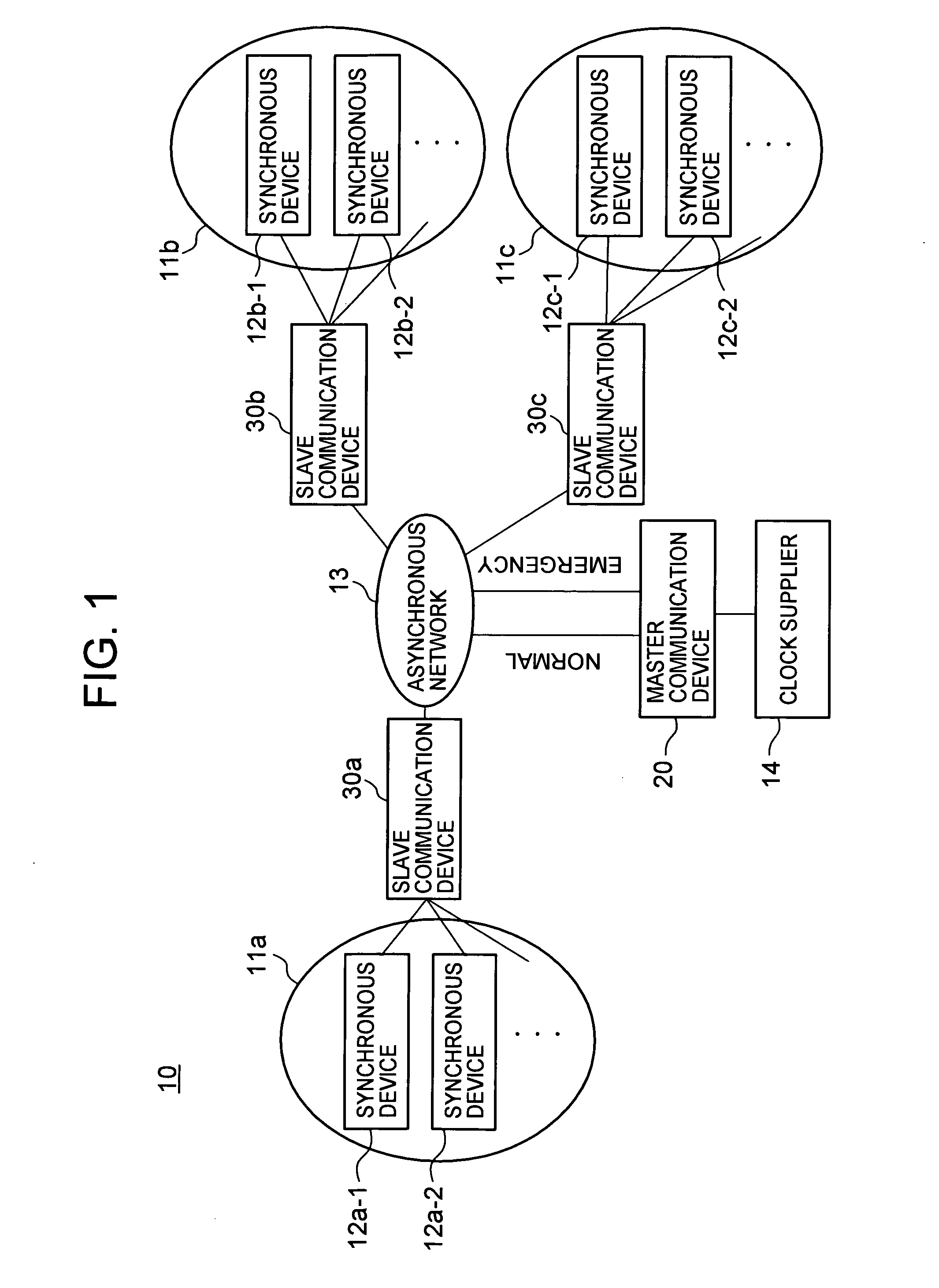
[0023]FIG. 1 shows the configuration of a communication system 10 according to an embodiment of the present invention. The communication system 10 has a clock supplier 14, a master communication device 20, and plural slave communication devices 30. The clock supplier 14 generates a reference clock having high frequency stability at a phase shift amount of 1×10⁻¹¹ or less, for example, and provides the reference clock to the master communication device 20.

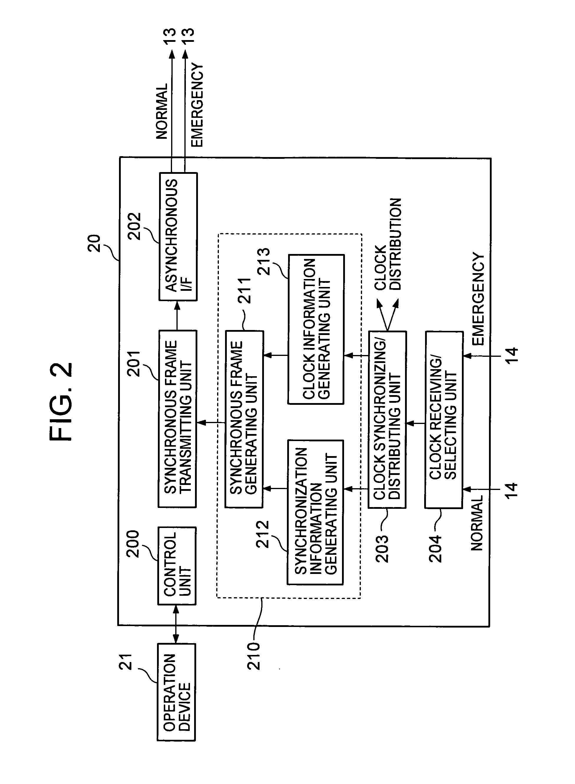
[0024] Based on the reference clock received from the clock supplier 14, the master communication device 20 generates a master clock which has a frequency used in synchronous communications such as asynchronous transfer mode (ATM) and which is a clock synchronized with the reference clock. The master communication device 20 generates a synchronization information frame which contains information about the generated master clock, and sends the generated...


PUM


Abstract

A communication system is provided which allows synchronous devices in different synchronous communication networks to have synchronous communications with one another via an asynchronous communication network. In the communication system of the present invention, a master communication device generates a master clock based on a reference clock which is provided by a clock supplier. The master communication device sends a synchronization information frame, which contains information about the generated master clock, to plural slave communication devices via the asynchronous communication network. The slave communication devices each reproduce the master clock from the received synchronization information frame.

Description

BACKGROUND OF THE INVENTION [0001] The present invention relates to a technique for synchronous communication through an asynchronous network. DESCRIPTION OF THE RELATED ART [0002] Synchronous digital hierarchy (SDH) is a known multiplexing method which can be applied with efficiency to various services dealing with audio (e.g., telephone services), images, and the like. A network which employs SDH is a synchronous network. If a communication device in one network using SDH is to communicate with a communication device in another network using SDH, the networks and communication devices have to be in sync with each other. [0003] A network is synchronized with another network by, for example, a method in which a clock generator which generates a reference clock of high precision delivers the reference clock to each network via a dedicated line, a method in which an upper level network generates a clock based on a reference clock and supplies the generated clock to a lower level netwo...

Claims


Application Information

Patent Timeline
Patent Type & Authority Applications(United States)
IPC IPC(8): H04L7/00
CPCH04J3/0664H04J3/0688H04J2203/0085H04L12/403
Inventor YASUDA, TAKESHIASHI, YOSHIHIROMUTOU, KEN
Owner HITACHI LTD
Learn More