Mechanically self actuated liquid level sensor

a self-actuating, liquid level sensor technology, applied in the direction of liquid/fluent solid measurement, machines/engines, instruments, etc., can solve the problems of erroneous reading, inconvenient measurement of liquid level, measuring float jamming in the tube, etc., to achieve the effect of eliminating the rotation feature of the handl

Inactive Publication Date: 2008-09-02
FLING JOHN J +1
View PDF30 Cites 10 Cited by
  • Summary
  • Abstract
  • Description
  • Claims
  • Application Information

AI Technical Summary

Benefits of technology

[0003]The present invention overcomes the problems described above in measuring liquid levels and eliminates the need for the person making the measurements to rotate the handle. The elimination of the handle rotation feature is extremely important in that current practice in the industry is to suspend the wooden dip sticks by a lanyard or a foldable handle into the tank opening allowing it to descend until the stick hits the bottom of the tank. The stick is then withdrawn, and the wet line on the stick is observed.
[0009]The springs that provide the locking pressure for the float lock guide cam preferably are attached to and distributed periodically along the entire length of the float lock guide-cam. These K-shaped springs provide spring force between the inner wall in a first side of the frame and the cam arm of the float lock guide cam. Each spring applies separate pressure to provide uniform spring loading at all points along the float's travel. This assures consistent locking of the float at all liquid levels.

Problems solved by technology

U.S. Pat. No. 4,802,363, which issued Feb. 7, 1989 to one of the present inventors, discloses an apparatus for measuring liquid level, which although satisfactory for some uses, is inconvenient for some situations that arise in measuring liquid levels.
If this center rectangular bar becomes even slightly bent, twisted or concentrically displaced due to rough usage, it can cause the measuring float to be jammed in the tube and give an erroneous reading.

Method used


Image

  • Mechanically self actuated liquid level sensor
  • Mechanically self actuated liquid level sensor
  • Mechanically self actuated liquid level sensor

Examples


Embodiment Construction

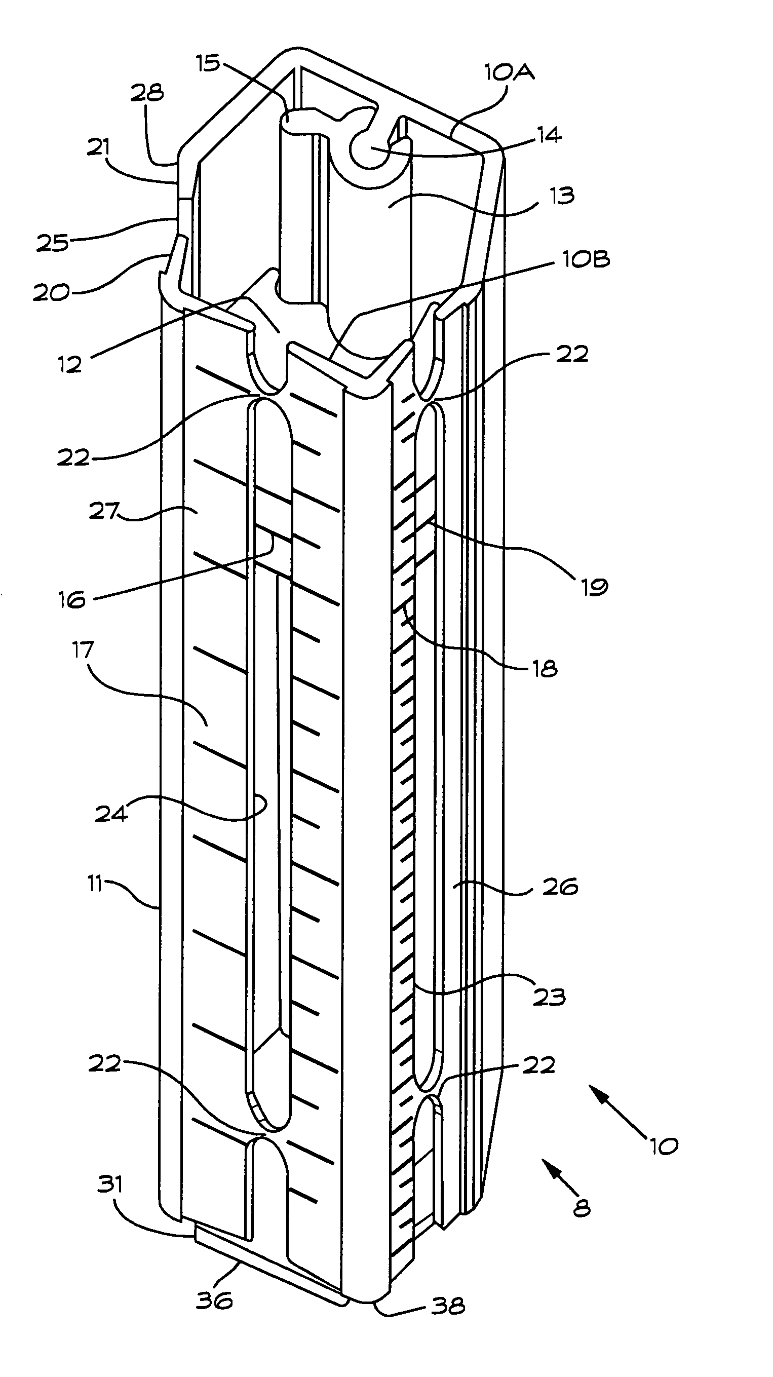
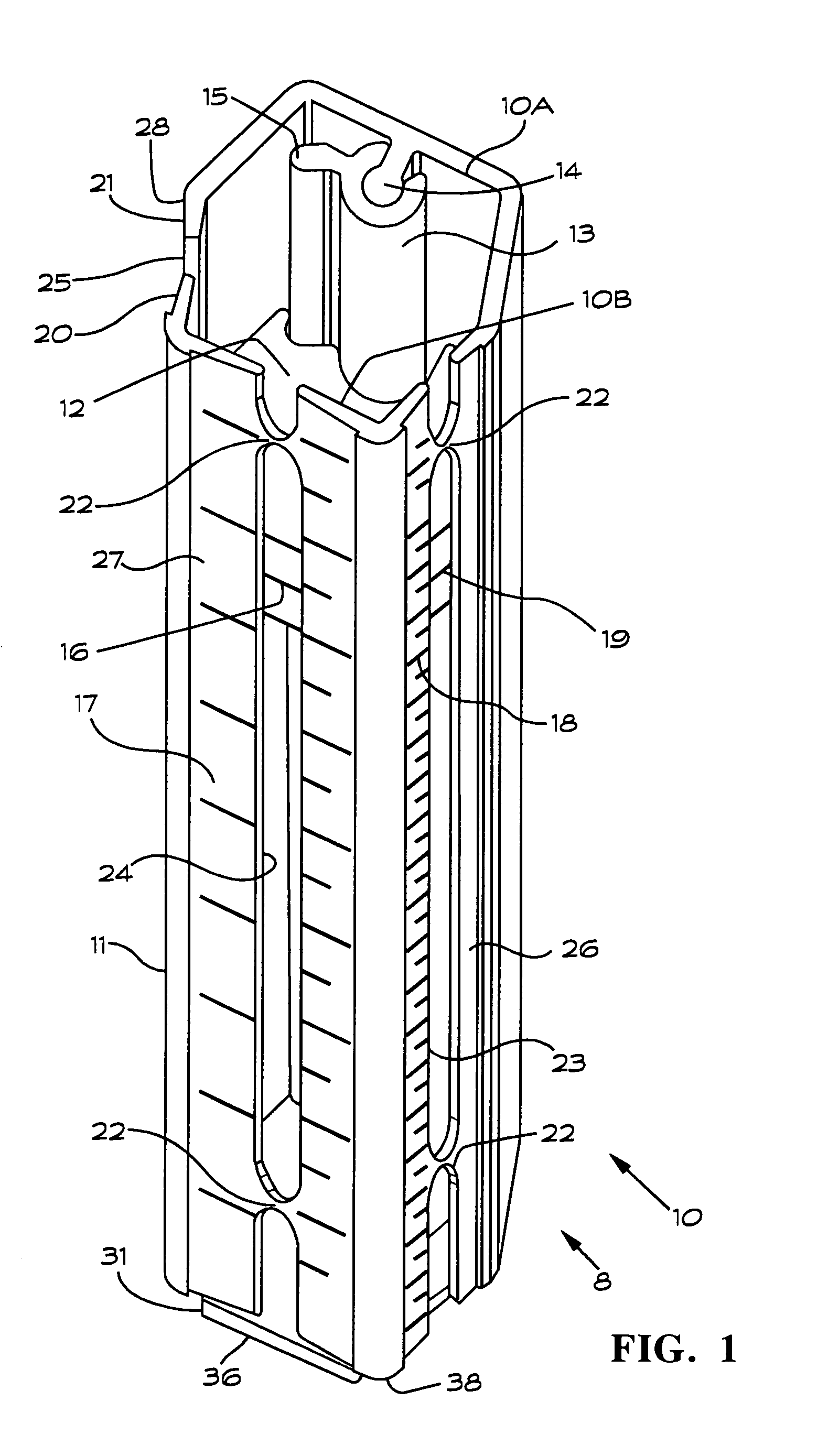
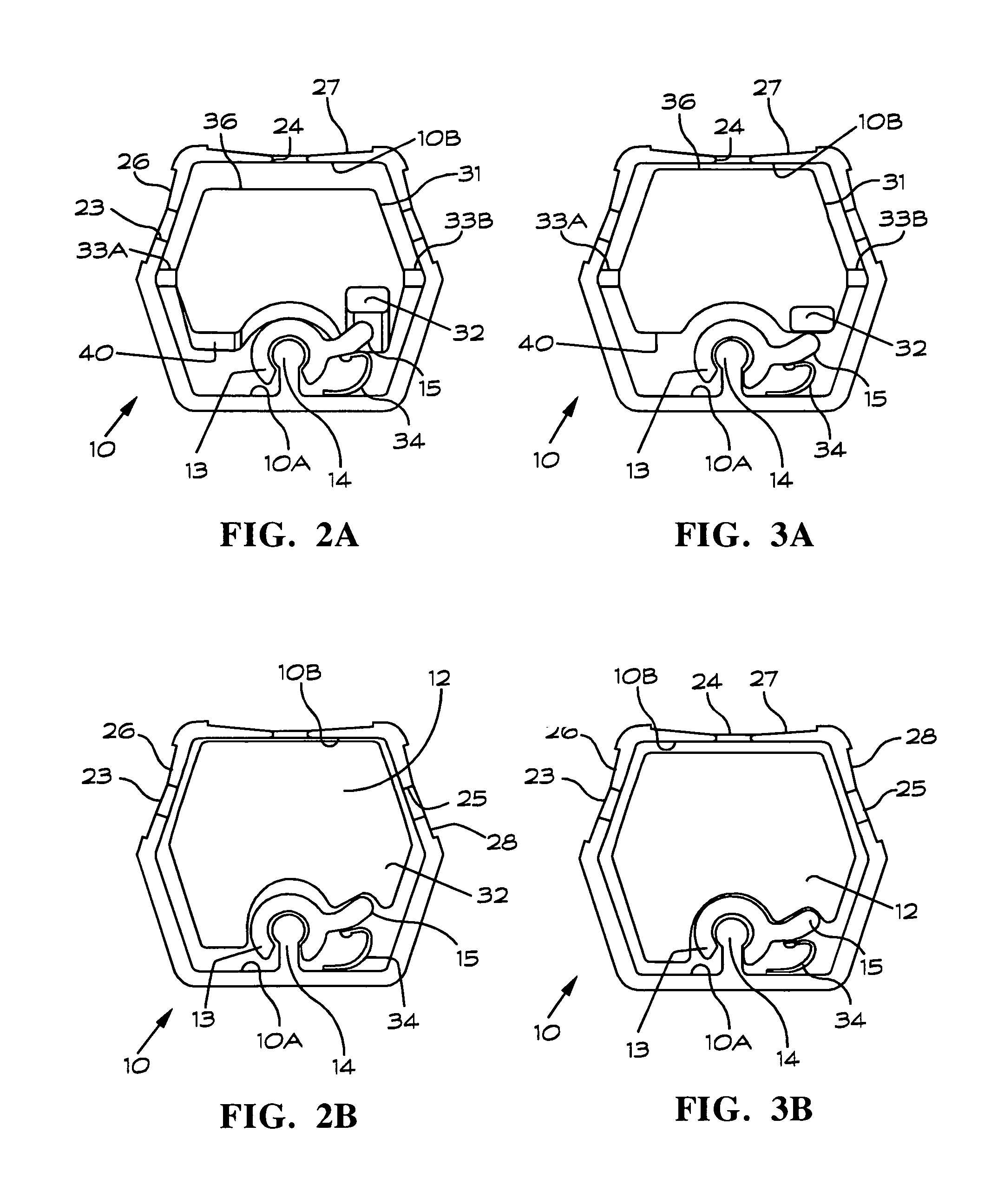
[0018]As shown in FIG. 1, a liquid level sensor 8 according to the invention has a frame 10. The frame 10 may have an elongate generally tubular configuration with a generally hexagonal shaped cross section. The frame 10 typically has a length of five to seventeen feet to be suitable for measuring liquid levels in underground and surface mounted tanks (not shown). The shorter version has application to measuring liquid levels in barrels. The form of the cross section of the frame 10 is best seen in FIGS. 2A, 2B, 3A, and 3B. The frame 10 is not limited to the cross section shown in the drawings. The invention may be readily practiced using a frame having other cross sectional shapes such as circular, triangular or rectangular, for example, depending on applications and user preferences.

[0019]The frame 10 has an inner wall 10A on which an extended cam pivot 14 is attached. A float lock guide cam 13 is pivotally attached to the extended cam pivot 14 as shown. Both the extended cam pivo...


PUM


Abstract

A liquid level sensor for measuring liquid levels in underground and above ground containers includes a frame formed to have an elongate hollow tubular configuration that encloses a cavity. A cam pivot has an end extending into the cavity from a first inner wall portion of the frame. A cam is arranged to be pivotal about the end of the cam pivot. A float is placed in the cavity. A spring is arranged to bias the cam arm into contact with the float to force a side portion of the float into a locked position in frictional engagement with the second inner wall portion of the frame. A cam actuator pivotally mounted in a lower end portion of the frame exerts a force on the cam arm to release the float from the locked position when the lower end of the frame contacts the container bottom.

Description

BACKGROUND OF THE INVENTION[0001]This invention relates generally to measuring liquid depth and particularly to measuring liquid level in containers located, both above and below ground.[0002]U.S. Pat. No. 4,802,363, which issued Feb. 7, 1989 to one of the present inventors, discloses an apparatus for measuring liquid level, which although satisfactory for some uses, is inconvenient for some situations that arise in measuring liquid levels. The device disclosed in U.S. Pat. No. 4,802,363 has a rectangular float that is centered in a rectangular tube. Using this device requires rotation of a handle to unlock the float so that it can float to the liquid surface. The rectangular bar that actuates this locking action must be precisely centered along the full length of the rectangular tube in order to assure that a false lock will not occur. If this center rectangular bar becomes even slightly bent, twisted or concentrically displaced due to rough usage, it can cause the measuring float ...

Claims


Application Information

Patent Timeline
Patent Type & Authority Patents(United States)
IPC IPC(8): G01F23/30
CPCG01F23/64
Inventor FLING, JOHN J.FLING, WILLIAM F.
Owner FLING JOHN J
Why Eureka
Try Eureka