Wedge assembly

a wedge and assembly technology, applied in the field of displacement limiting systems, can solve the problems of non-parallel deflection, additional vehicle noise, undesirable match-boxing, etc., and achieve the effect of reducing the sound level of the interior vehicle, sliding the wedge, and improving the acoustic performance of the vehicl

Active Publication Date: 2006-09-14
NEWFREY
View PDF35 Cites 9 Cited by
  • Summary
  • Abstract
  • Description
  • Claims
  • Application Information

AI Technical Summary

Benefits of technology

[0009] Wedge assemblies of the present invention provide several advantages. By eliminating the harder plastic sliding wedges of known wedge assemblies and replacing the sliding wedge with a deflectable elastomeric material wedge, acoustic performance of the vehicle is improved, including reduction of the interior vehicle sound level due to drive train “boom”. The deflectable elastomeric material wedge of the present invention also allows the sliding feature of previous designs to be eliminated, together with the spring or biasing element normally used to allow the wedge to slide. This reduces the number of parts, including eliminating the over-slam bumper previously used, and therefore the cost of the present invention wedge assemblies. The detrimental effects of dirt and similar materials which could previously effect the sliding motion of the wedge are reduced using a deflectable wedge of the present invention. Wedge assemblies of the present invention also provide an anti-chucking feature.

Problems solved by technology

Motion of the vehicle therefore can result in “match-boxing”, or non-parallel deflection of the support posts relative to the squared sides of the lift-gate door.
Match-boxing is undesirable for several reasons.
First, side-to-side or non-parallel motion of support posts can impart additional vehicle noise, known as “chucking” at the lift-gate latch as the vehicle travels along rough or uneven surfaces.
Second, vehicle drive train vibration known as idle or “drive train boom” can be transmitted as noise into the passenger compartment via known sliding wedge designs.
Third, unless a mechanism is positioned between the lift-gate door edge and the support posts of the vehicle, full structural allowance for the stiffness of the lift-gate cannot be used in the design of the support structure area.
Common designs for sliding wedge assemblies have several problems.
First, vehicle rattling noise is produced if the slide is not maintained in continuous contact with the striker plate (or vehicle support post) throughout the travel length of the slide.
Tolerances used for common wedge assembly slides permit easy translation, but can result in rattling between the parts during vehicle travel.
Second, vehicle build variation, vehicle manufacturing tolerances and / or frame vertical deflection during vehicle use can contribute to a disconnect or non-contact between the slide and the striker plate (or vehicle support post).
If the slide is not maintained in contact with the vehicle support post or striker plate, rattling can occur.
Third, contaminants such as dirt which contact portions of the wedge assembly could prevent the slide from moving freely, thus potentially resulting in increased chucking and / or increased lift-gate closing effort.
Fourth, the hard plastic material commonly used for sliding wedge designs may not dampen the vibration caused by the drive train during idle operation, thus further contributing to drive train boom.

Method used


Image

  • Wedge assembly
  • Wedge assembly
  • Wedge assembly

Examples


Embodiment Construction

[0023] The following description is merely exemplary in nature and is in no way intended to limit the invention, its application, or uses.

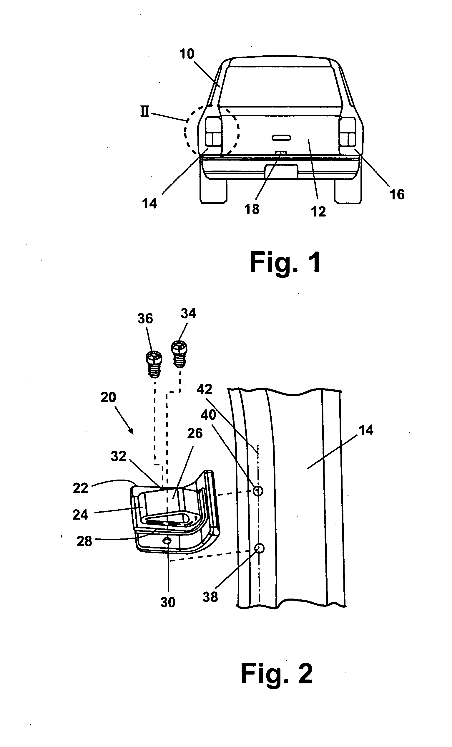
[0024] According to one preferred embodiment of the present invention and referring to FIG. 1, a vehicle 10 includes a rear lift-gate door 12 positioned between both a left support post 14 and a right support post 16 of vehicle 10. A latch 18 is generally provided about mid span along a bottom edge of rear lift-gate door 12. Side edges of rear lift-gate door 12 adjacent to left support post 14 and right support post 16, respectively, are generally not latched or otherwise connectable to left support post 14 or right support post 16.

[0025] As best seen in FIG. 2, a wedge sub-assembly 20 having a wedge support member 22 is supported from left support post 14. Wedge support member 22 is preferably provided of a “hard” polymeric material, for example a glass fiber reinforced polyamide material such as nylon 6-6, molded into the configuration shown. ...


PUM


Abstract

A vehicle door wedge assembly has an elastomeric wedge connected to a first member, and a second member. A wedge perimeter wall has exterior facing and engagement portions, and an interior wall equidistantly spaced from the engagement portion. The interior and engagement walls define an interior cavity. The exterior facing wall deflects into the interior cavity during engagement of the first and second members.

Description

FIELD OF THE INVENTION [0001] The present invention relates in general to displacement limiting systems and more specifically to a device and method for coupling use for vehicle door wedge systems. BACKGROUND OF THE INVENTION [0002] Vehicles including automobile sport utility vehicles, station wagons, mini-vans, cross-over vehicles, cargo vans and trucks often provide an access door, commonly known as a lift-gate door. Other similar door designs include hatchback doors, sliding doors and horizontally swinging doors. Although these door designs can be mounted differently, for simplicity, these door designs will hereinafter be summarized in reference to lift-gate doors. Lift-gate doors are frequently hinged along an upper horizontal surface, and latch adjacent to a flooring system of the automobile, commonly adjacent to the rear fender of the automobile. One or more latches can be used. The side edges of lift-gate doors are generally not hinged or physically connected to the vehicle s...

Claims


Application Information

Patent Timeline
Patent Type & Authority Applications(United States)
IPC IPC(8): E05F5/06
CPCE05F5/022E05F7/04Y10T16/628Y10T16/629E05Y2900/531E05D15/00
Inventor SCHUBRING, GARY L.MOKASHI, GIRISHSINGH A.
Owner NEWFREY
Why Eureka
Try Eureka