
Swivel inlet hose-drag linear irrigation machine

a linear irrigation machine and hose-dragging technology, which is applied in watering devices, horticulture, agriculture, etc., can solve the problems of limited hose pulling capability of the cart, time-consuming and labor-intensive,

Active Publication Date: 2008-09-02
VALMONT INDUSTIES INC
View PDF7 Cites 18 Cited by
  • Summary
  • Abstract
  • Description
  • Claims
  • Application Information

AI Technical Summary

Benefits of technology

[0007]The swivel inlet hose-drag irrigation machine of this invention uses an inlet elbow mounted in a swivel bearing to attach the water supply hose to the machine. The inlet elbow is mounted out to the side of the four-wheel linear cart rather than behind the cart between the tires. The inlet elbow is free to rotate in an approximate 180° arc so that the hose can be attached from either end of the cart at the side thereof. In this way, the hose never needs to be disconnected from the cart because the elbow can simply be rotated around to face the opposite direction. An attractive feature is for the elbow to automatically swivel to the other side as the machine reverses, so the operator need not be present. This is accomplished by biasing the elbow outward away from the cart at a small angle so that when the machine is reversed and begins to push the polyethylene hose backwards, there will be a small component of force causing the elbow to rotate. The polyethylene hose has weight and stiffness enough to push the elbow around. As the machine reverses, the polyethylene hose is pushed outwardly away from the cart, the elbow rotates as necessary, and the polyethylene hose eventually trails behind the inlet elbow as the machine continues down its path in the opposite direction. The instant invention also includes means for pushing the drag hose out of the way of the tires of the machine.

Problems solved by technology

This is time-consuming and labor intensive and is a main reason that hose-drag linear machines are not used by more customers.
In some cases, two-wheel hose drag units have been utilized, but the hose pull capability of those carts is limited due to the light weight thereof and the lack of traction thereof.

Method used


Image

  • Swivel inlet hose-drag linear irrigation machine
  • Swivel inlet hose-drag linear irrigation machine
  • Swivel inlet hose-drag linear irrigation machine

Examples


Embodiment Construction

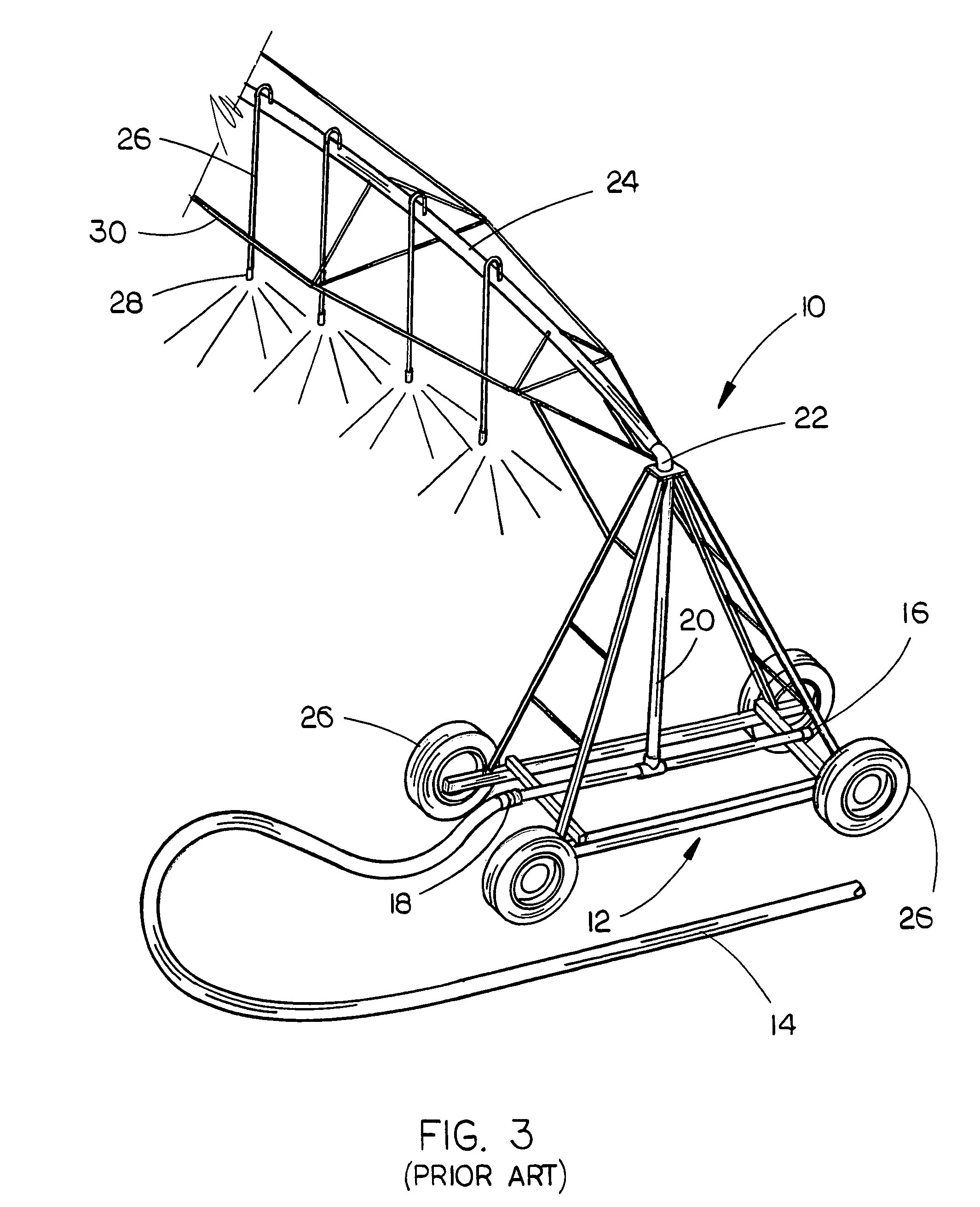
[0022]Referring to FIG. 3 wherein a prior art hose-drag linear irrigation machine or system 10 is shown, the numeral 12 refers to a four-wheel cart which normally has a platform on which an engine, generator or oil pump and various panels are mounted, but the platform and items mounted thereon are not shown for reasons of clarity. Water from a conventional hydrant enters hose 14, which is connected to cart 12 at either point 16 or 18. The water then flows up vertical feed pipe 20 to an elbow connection 22, thence out into a main water line 24 which is supported upon a plurality of spaced-apart self-propelled drive towers or units in conventional fashion. The water flows through drops 26 to spray nozzles 28 where it is sprayed onto crops. The drops 26 and nozzles 28 are frequently replaced with other spray devices positioned on water line 24. The main water line 24 is supported by a truss structure 30. Cart 12 includes wheels 26, some of which or all of which are driven for propellin...


PUM


Abstract

A swivel inlet hose-drag irrigation machine is disclosed which utilizes an inlet elbow mounted in a swivel bearing on the cart to attach a water supply hose to the machine. The inlet elbow is mounted to the side of the four-wheel linear cart rather than behind the cart between the tires. The inlet elbow is free to rotate in a 180° arc so that the hose can be attached from either end of the cart at the side thereof. The machine also includes a pair of vertically disposed and rotatable rollers which are mounted at the opposite ends of the cart to push the drag hose out of the way of the tires of the cart so that the tires of the cart do not roll over the drag hose thereby eliminating any manual handling of the drag hose.

Description

CROSS-REFERENCE TO RELATED APPLICATION[0001]This application claims the benefit of U.S. Provisional Application Ser. No. 60 / 831,474 entitled SWIVEL INLET HOSE-DRAG LINEAR IRRIGATION MACHINE filed Jul. 18, 2006, the disclosure of which is hereby incorporated herein by reference.BACKGROUND OF THE INVENTION[0002]1. Field of the Invention[0003]This invention relates to a linear move irrigation system and more particularly to a swivel inlet hose-drag linear irrigation machine.[0004]2. Description of the Related Art[0005]FIGS. 1 and 2 illustrate a prior art linear move irrigation machine or system, such as disclosed in U.S. Pat. No. 4,172,551. As seen in FIGS. 1 and 2, the prior art machine generally comprises an elongated water conduit which extends over the field to be irrigated and which is supported by a series of support towers spaced along the length thereof. Each of the support towers is self-propelled so that the conduit may be moved across the field to be irrigated. The linear mo...

Claims


Application Information

Patent Timeline
IPC IPC(8): B05B3/18B05B3/00
CPCA01G25/092
Inventor THEILEN, DENNIS R.
Owner VALMONT INDUSTIES INC
Features
  • Generate Ideas
  • Intellectual Property
  • Life Sciences
  • Materials
  • Tech Scout
  • Unparalleled Data Quality
  • Higher Quality Content
  • 60% Fewer Hallucinations
Learn More