Seal assembly and method of manufacturing the same

a technology of sealing assembly and assembly method, which is applied in the direction of engine seals, mechanical devices, engine components, etc., can solve the problems of comparatively low wear and abrasion resistance of ptfe and high cost, and achieves higher wear and abrasion resistance materials, less flexible effects

Inactive Publication Date: 2008-09-02
FEDERAL MOGUL WORLD WIDE
View PDF35 Cites 17 Cited by
  • Summary
  • Abstract
  • Description
  • Claims
  • Application Information

AI Technical Summary

Benefits of technology

[0006]One advantage of this seal assembly is the ability to use non-PTFE bearing grade plastic material for the sealing element. This provides a substantial cost savings over traditional materials such as PTFE, while providing a higher wear and abrasion resistant material suitable for dynamic fluid sealing. Traditionally, such materials have not been used for sealing elements given the rigid nature of such materials, i.e., as the shaft becomes misaligned in the bore the sealing element wears unevenly thus deteriorating the sealing relation with the shaft. With the seal assembly of the present invention, the flexible member is able to flex as the shaft becomes misaligned in the bore. Thus, the sealing element, which is retained by the flexible member, can be less flexible, since the sealing element moves with the flexible member.
[0007]In another aspect of the present invention, the sealing element extends in a plurality of helically wound convolutions about the outer running surface. The convolutions provide a hydrodynamic effect which acts as a pump to redirect any fluid that finds its way under the seal back toward the interior (“oil side”) of the seal. The convolutions can be single or multiple start thread form, and can be uni or bi-directional, if desired.
[0008]The present invention further provides a method of manufacturing a seal assembly with the plurality of helically wound convolutions. The method includes forming a groove extending helically within a surface of a stock piece of sealing material to define a fracture line within the stock piece. The stock piece is then fractured along the fracture line to form the sealing element. By forming the groove to define the fracture line, the method of manufacturing the seal assembly provides a simple and cost effective procedure for forming the sealing element with the plurality of convolutions.

Problems solved by technology

However, PTFE has comparatively low wear and abrasion resistance and is costly, limiting its use to only certain sealing applications or requiring extra measures to protect the PTFE from damage from the environment.

Method used


Image

  • Seal assembly and method of manufacturing the same
  • Seal assembly and method of manufacturing the same
  • Seal assembly and method of manufacturing the same

Examples


Embodiment Construction

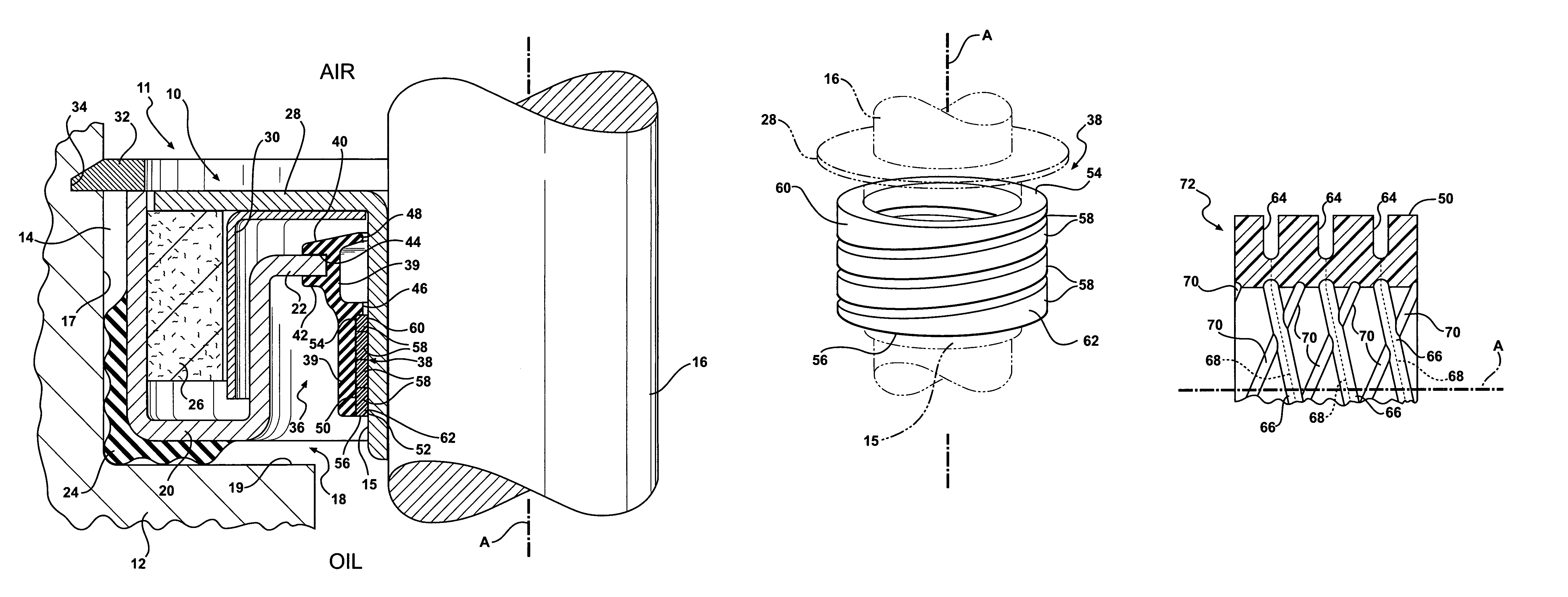
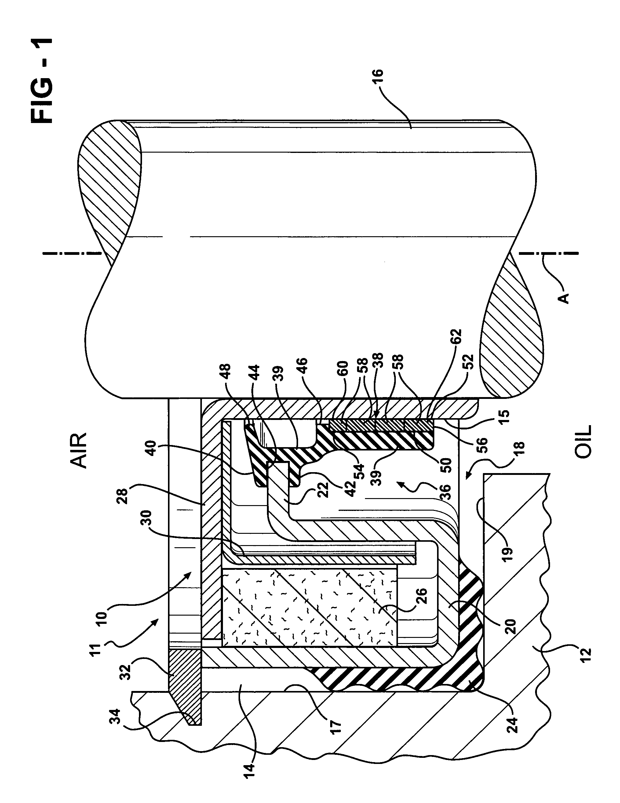
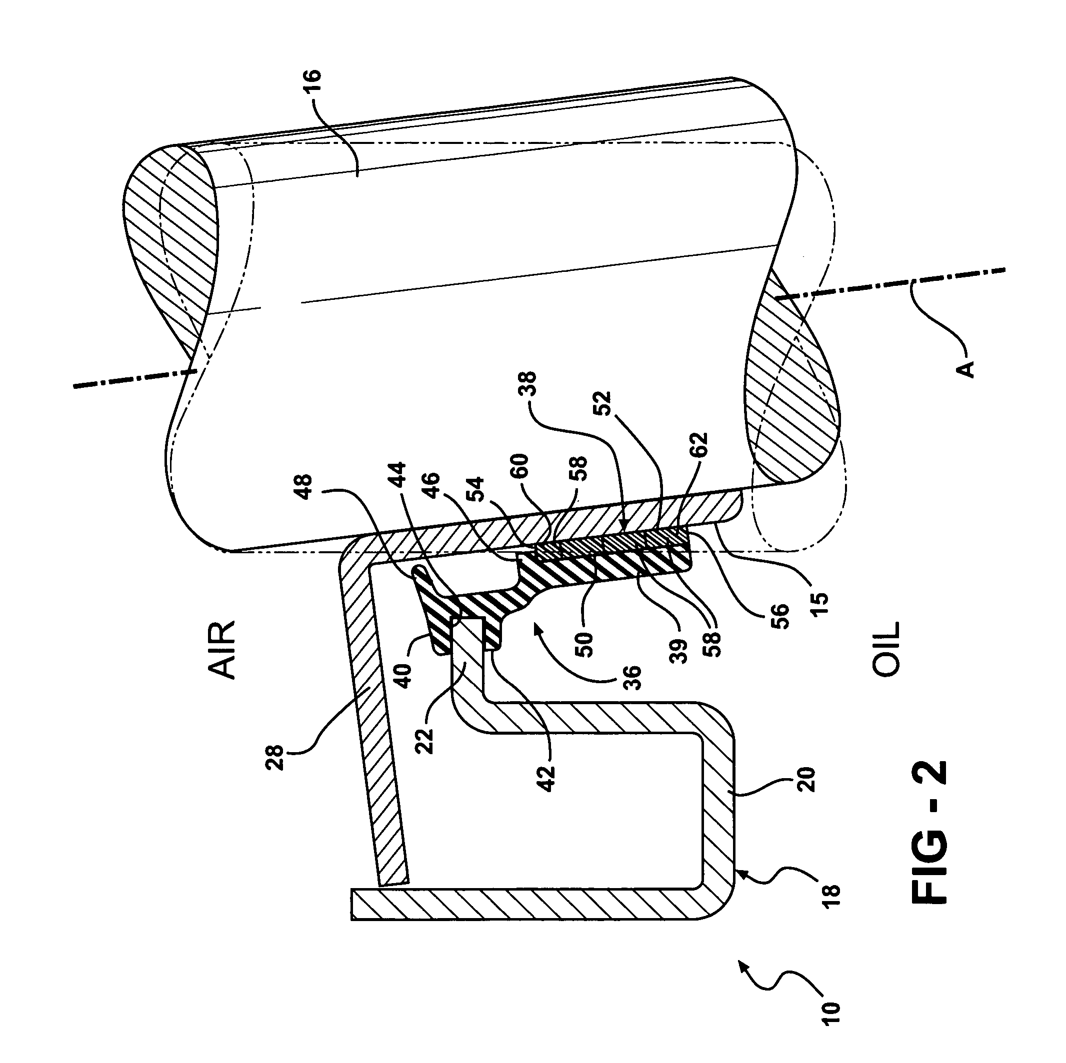
[0018]Referring to the Figures, wherein like numerals indicate like or corresponding parts throughout the several views, a seal assembly of the present invention is generally shown at 10. The seal assembly 10 is well suited for a multitude of applications in which a dynamic fluid seal is required. Such applications may include automotive and industrial applications. The seal assembly 10 is illustrated herein for use in a shaft seal system 11.

[0019]With reference to FIG. 1, the shaft seal system 11 uses the seal assembly 10 to provide a dynamic fluid seal between a housing 12 having a bore 14 and a shaft 16 having an outer running surface 15 rotating within the bore 14. The outer running surface 15 rotates about an operational axis A relative to the housing 12. In FIG. 1, the outer running surface 15 is presented by an annular wear sleeve 28 that is press fit to the shaft 16. The wear sleeve 28 is press fitted to the shaft 16 for purposes well-known to those skilled in the art, such ...


PUM

PropertyMeasurementUnit
compressive strengthaaaaaaaaaa
tensile strengthaaaaaaaaaa
flexibleaaaaaaaaaa

Abstract

A seal assembly and method for the manufacture thereof is provided. The seal assembly provides a dynamic fluid seal between a housing having a bore and a shaft having an outer running surface rotating within the bore. The seal assembly comprises a rigid carrier for supporting the seal assembly within the bore of the housing. A flexible member is mounted to the rigid carrier. The flexible member is formed from an elastomeric material that allows the flexible member to flex during use. A sealing element is retained by the flexible member about the outer running surface. The sealing element is formed from a non-polytetrafluoroethylene bearing grade plastic material having a hardness relatively greater than a hardness of the elastomeric material of the flexible member. The sealing element moves with the flexible member as the flexible member flexes. The sealing element extends along the outer running surface in a plurality of helically wound convolutions.

Description

FIELD OF THE INVENTION[0001]The present invention relates generally to seal assemblies used to provide a dynamic fluid seal between a housing and a shaft having an outer running surface rotating relative to the housing. More specifically, the present invention relates to sealing elements used in such seal assemblies, including the materials and shapes used to form such sealing elements, and the method for manufacturing such sealing elements.BACKGROUND OF THE INVENTION[0002]Seal assemblies are well known for providing a dynamic fluid seal between a housing having a bore and a shaft having an outer running surface protruding through the bore and rotating relative to the housing. Such seal assemblies typically comprise a rigid carrier for supporting the seal assembly in the bore. A mounting collar formed from rubber is often molded about the rigid carrier to provide a press-fit connection between the seal assembly and the housing thereby aligning the seal assembly within the bore about...

Claims


Application Information

Patent Timeline
Patent Type & Authority Patents(United States)
IPC IPC(8): F16J15/32
CPCF16J15/3224F16J15/3264Y10T29/49297Y10T29/49826Y10T29/49906Y10T29/49881F16J15/32F16J15/34
Inventor TOTH, DAVID M.HATCH, FREDERICK
Owner FEDERAL MOGUL WORLD WIDE
Why Eureka
Try Eureka