
Animated timepiece

a timepiece and animation technology, applied in the field of timepiece movement, can solve the problems of occupying a great deal of space for the mechanical parts,

Inactive Publication Date: 2008-09-02
CHRISTOPHE CLARET
View PDF14 Cites 0 Cited by
  • Summary
  • Abstract
  • Description
  • Claims
  • Application Information

AI Technical Summary

Benefits of technology

"The present invention provides a space-saving and reliable alternative to known mechanisms of the prior art. It allows for the display of information stealthily and at a speed that ensures its visibility. The invention includes a horological movement with a cam that acts on locking means to release the second wheel-and-pinion unit for stealthy rotation through a predefined angle. A retarding device acts on the second wheel-and-pinion unit to limit its speed of stealthy rotation. The movement imposes no great constraints on its manufacturer, and it allows for the stealthy display of a sign, improving its visibility to the wearer of the timepiece. The invention also includes a timepiece with the movement."

Problems solved by technology

However, these mechanisms sometimes take up a great deal of space, are often sensitive to shocks, and can transmit only very sudden movements to the intermittently driven indicator member.

Method used


Image

  • Animated timepiece
  • Animated timepiece

Examples


Embodiment Construction

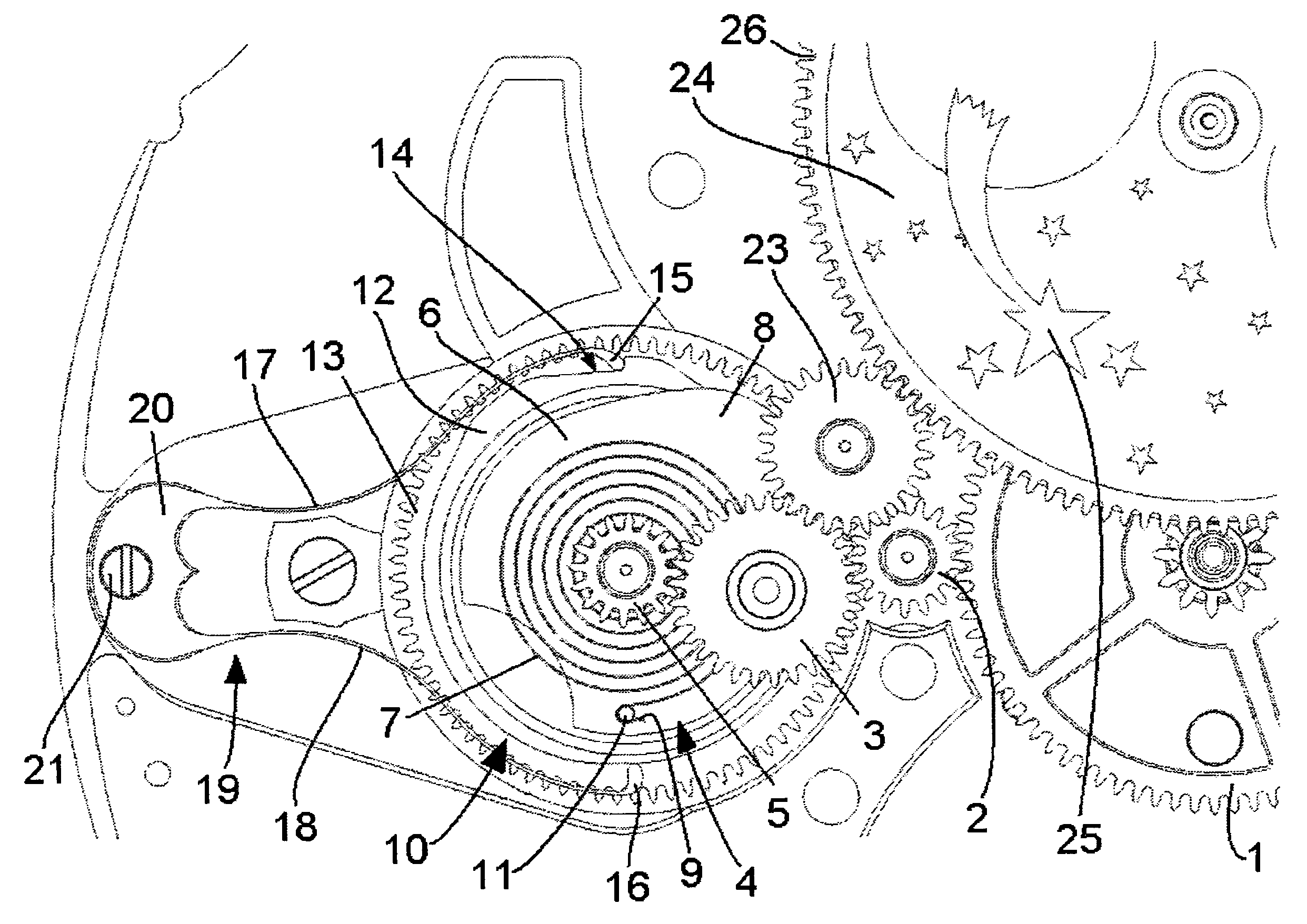
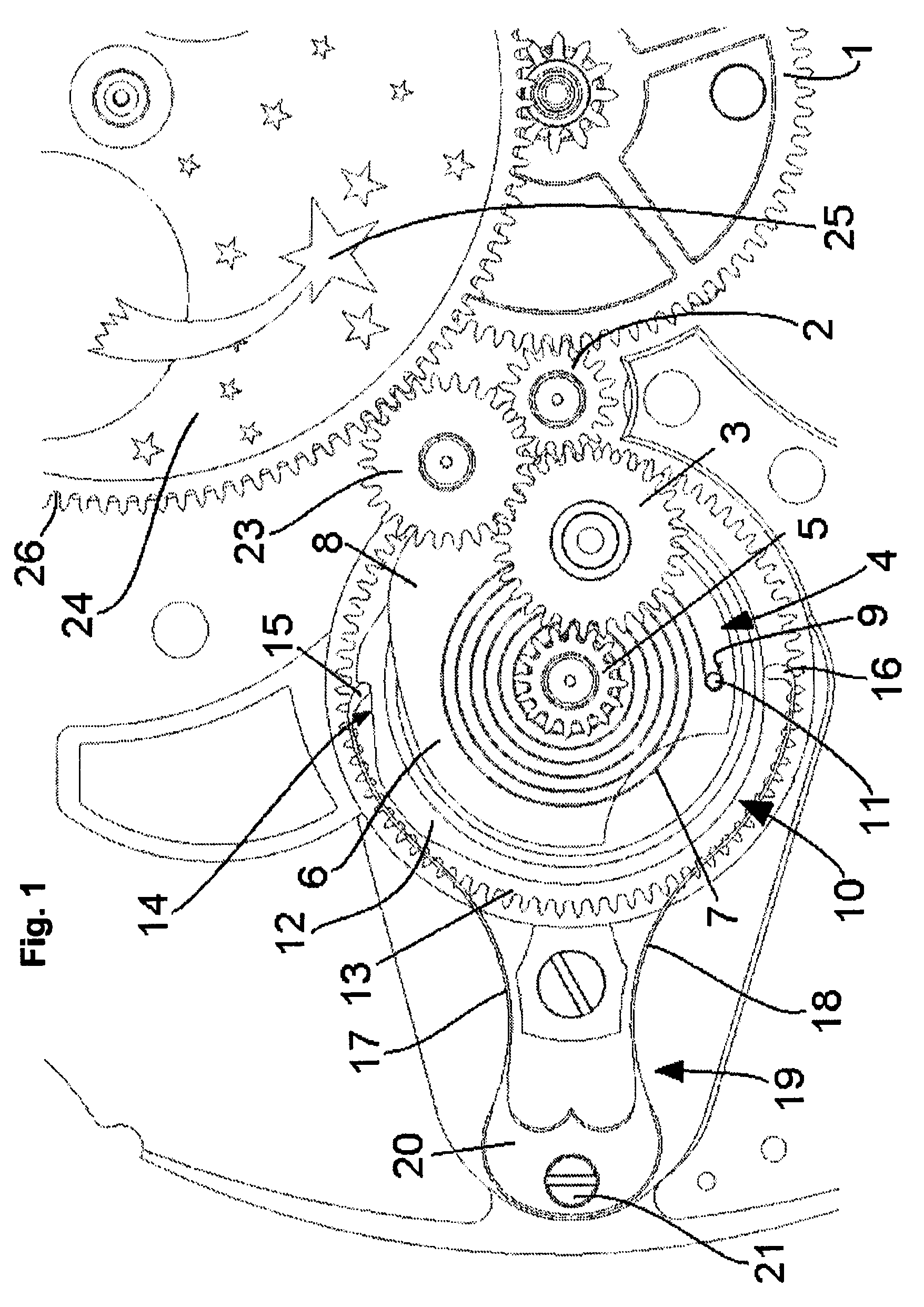
[0026]FIG. 1 shows part of a center wheel 1 driven in a clockwise direction and engaging, via two intermediate gears 2 and 3, with a first wheel-and-pinion unit 4.

[0027]The first wheel-and-pinion unit comprises a pinion 5 connected coaxially to a cam 6, and carries a first end (not visible) of a spiral spring 7. The general shape of the cam is a disk, of predefined radius, part of its periphery being extended to define a nose 8. In the central region of its nose, therefore, the radius of the cam is greater than its average radius.

[0028]The other end 9 of the spiral spring is fixed to a second wheel-and-pinion unit 10 mounted coaxially with the first wheel-and-pinion unit. More precisely, the end 9 is secured to a pin 11 carried by a drive wheel 12 of this second wheel-and-pinion unit. The latter also comprises a lower wheel 13 coaxial with and secured to the drive wheel 12.

[0029]The drive wheel has a notch 14 designed to receive in alternation the diametrically opposed free ends 15 ...


PUM


Abstract

A timepiece movement is disclosed which may comprise a going train, and a mechanism having a first cinematic connection with the going train and arranged to drive an indicator member in a stealthy rotational movement, the latter being activated periodically with a predefined period. The mechanism may also comprise a first wheel-and-pinion unit comprising a first wheel at least indirectly in engagement with the going train, a second wheel-and-pinion unit, mounted coaxially with the first wheel-and-pinion unit and, having at least one stop region and a second wheel, these being integral in rotation. A second cinematic connection connects the second wheel to the indicator member, an elastic member connecting the first wheel-and-pinion unit to the second wheel-and-pinion unit in such a way that its degree of tension is a function of respective angular positions of the first and second wheel-and-pinion units. The mechanism may further comprise locking means designed to prevent the second wheel-and-pinion unit from rotating between two successive movements of the indicator member, as well as release means designed to act on the locking means, in each period, in order to release them momentarily and permit stealthy rotation of the second wheel-and-pinion unit through a predefined angle The mechanism may also comprise a retarding device acting on the second wheel-and-pinion unit in such a way as to limit its speed of stealthy rotation.

Description

BACKGROUND OF THE INVENTION[0001]1. Field of the Invention[0002]The field of this disclosure is horology. It relates more particularly to a timepiece movement comprising a mechanism arranged to drive an indicator member in a stealthy rotational movement activated periodically, with a predefined period.[0003]In this text, the use of the term “stealthy” in relation to the notion of period should be understood to relate to an event whose duration is much shorter than this period. A non-restrictive example would be that the rotational movement is activated once every minute and each activation lasts for three seconds.[0004]More precisely, the horological movement comprises a going train, the mechanism also comprising[0005]a first wheel-and-pinion unit comprising a first wheel at least indirectly in engagement with the going train,[0006]a second wheel-and-pinion unit mounted coaxially with the first wheel-and-pinion unit, having at least one stop region and a second wheel, these being in...

Claims


Application Information

Patent Timeline
Patent Type & Authority Patents(United States)
IPC IPC(8): G04B19/00G04B19/02G04B19/26
CPCG04B13/002G04B45/0023G04B19/268
Inventor CLARET, CHRISTOPHEDUBOIS, JANKOUKJIAN, PIERRE
Owner CHRISTOPHE CLARET
Learn More