Drive system switching control method

a technology of driving system and control method, which is applied in the direction of steering initiation, instruments, vessel construction, etc., can solve the problems of not revealing a structure for inhibiting the switching operation, affecting the attitude of the vehicle body, and not being able to move desirable, etc., and achieve the effect of maintaining stably good attitud

Inactive Publication Date: 2008-09-02
SHOWA CORP
View PDF8 Cites 2 Cited by
  • Summary
  • Abstract
  • Description
  • Claims
  • Application Information

AI Technical Summary

Benefits of technology

[0010]In view of the above, an object of the present invention is to provide a drive system switching control method of an automotive four-wheeled vehicle by which a vehicle can travel while always keeping a vehicle body in a good attitude and in a dynamically balanced position turning, while at the same time stably maintaining the good attitude.
[0012]Since the switching of the drive system is inhibited at the time the vehicle turns such that the angle of steering is more than the predetermined angle, the motion by the switching does not have an adverse effect on the turning vehicle body. It is possible to drive the vehicle while always keeping the vehicle body in a good attitude and in a dynamically balanced position, while at the same time stably maintaining the good attitude.
[0014]The drive state at the angle of steering and the vehicle speed by which the vehicle body motion is not generated by switching the drive system is previously determined. The switching of the drive system is inhibited at the time of comparing the detected angle of steering with the vehicle speed and determining that the switching of the drive system is not allowed. The motion by switching the drive system does not have an effect on the turning vehicle body. It is possible to drive the vehicle while always keeping the vehicle body in a good attitude and in a dynamically balanced position, while at the same time stably maintaining the good attitude.
[0016]The relationship of the allowable angle of steering in correspondence to the vehicle speed by which the vehicle body attitude is not affected by switching the drive system is previously determined. The switching of the drive system is inhibited at the time of comparing the vehicle speed detected by the relationship. The allowable angle of steering is determined in correspondence to the vehicle speed. Where the detected angle of steering is more than the determined allowable angle of steering, the motion by switching the drive system does not have an effect on the turning vehicle body. It is possible to drive the vehicle while always keeping the vehicle body in a good attitude, and in a dynamically balanced position while at the same time stably maintaining the good attitude.

Problems solved by technology

However, this document does not disclose a structure for inhibiting the switching operation.
However, with respect to the control of the electromagnetic clutch, this document only discloses that the driven shaft is disconnected from the drive shaft when braking the vehicle.
If this motion is generated during a turning travel, an attitude of the vehicle body is affected so as to become unstable.
Accordingly, this motion is not desirable.

Method used


Image

  • Drive system switching control method
  • Drive system switching control method
  • Drive system switching control method

Examples


Embodiment Construction

[0039]A description will be given below of an embodiment in accordance with the present invention with reference to FIGS. 1 to 14.

[0040]An automotive four-wheeled vehicle in accordance with the present embodiment is a bar handle type buggy four-wheeled vehicle. It is provided with a drive transmission apparatus 1 in which a drive system switching clutch mechanism 2 and a differential mechanism 3 in a rear wheel side are integrally assembled.

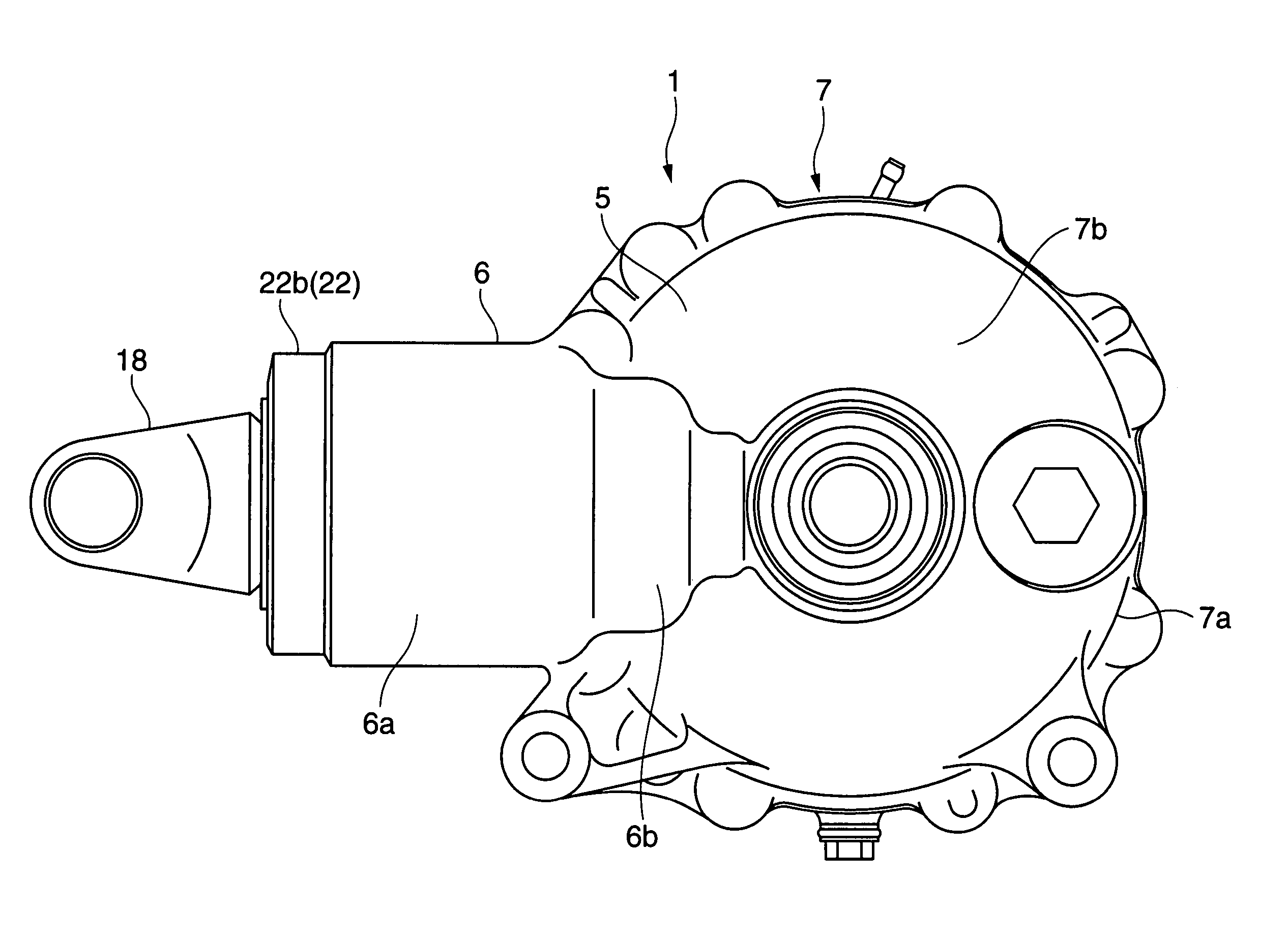
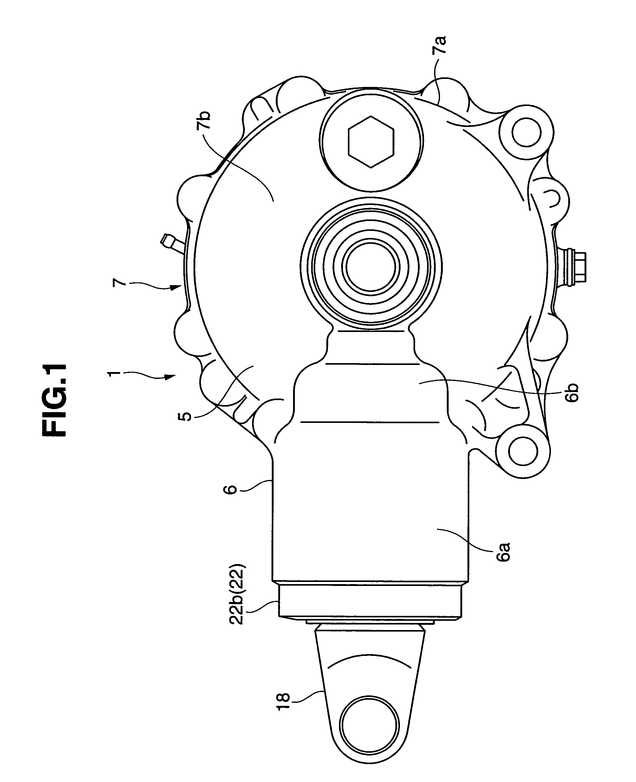
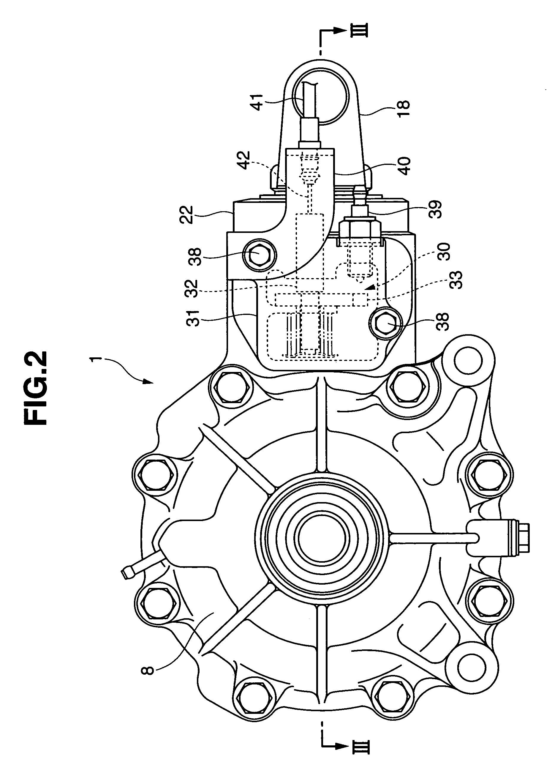
[0041]The drive transmission apparatus 1 has approximately the same structure as the drive transmission apparatus in accordance with the prior application filed by the same applicant of the present application. The description is given of the drive transmission apparatus 1 by showing a left side elevational view in FIG. 1, a right side elevational view in FIG. 2, and a cross sectional view in FIG. 3 (a cross sectional view cut along a line III-III in FIG. 2).

[0042]A gear case 5 is structured such that a clutch case 6 in a front half portion and a...


PUM


Abstract

In a drive system switching control method of an automotive four-wheeled vehicle for switching two drive systems comprising a two-wheel drive and a four-wheel drive. The method has a step of detecting a steering angle, and a step of inhibiting the drive system switching if the detected steering angle is over a predetermined angle.

Description

BACKGROUND OF THE INVENTION[0001]1. Field of the Invention[0002]The present invention relates to a drive system switching control method of an automotive four-wheeled vehicle which can switch between two drive systems comprising a two-wheel drive and a four-wheel drive.[0003]2. Description of the Related Art[0004]With respect to a switching apparatus of an automotive four-wheeled vehicle which can switch between two drive systems comprising the two-wheel drive and the four-wheel drive, the drive system is normally switched by always connecting one of either the front wheels or the rear wheels to a drive source and switching another thereof based on engaging and disengaging a clutch mechanism.[0005]In order to engage and disengage the clutch mechanism, there is an example in which a driver manually engages and disengages the clutch mechanism. See Japanese Patent Application Laid-Open No. 2000-264091 reference document 1. There is another example in which an electromagnetic coil or th...

Claims


Application Information

Patent Timeline
Patent Type & Authority Patents(United States)
IPC IPC(8): G06F17/00B60K17/34B60K23/08
CPCB60K23/08B60W2520/10B60W2540/18
Inventor TERADA, EIICHI
Owner SHOWA CORP
Why Eureka
Try Eureka