Damper unit for vessel propulsion apparatus, propeller for vessel propulsion apparatus, and vessel propulsion apparatus

a technology for propulsion apparatus and damper unit, which is applied in the direction of marine propulsion, propulsive elements, and vessel construction, can solve the problems of difficult to significantly improve the performance of the damper unit, and achieve the effect of minimizing the output of the vessel propulsion apparatus and reducing the area of the exhaust passag

Active Publication Date: 2016-07-26
YAMAHA MOTOR CO LTD
View PDF21 Cites 0 Cited by
  • Summary
  • Abstract
  • Description
  • Claims
  • Application Information

AI Technical Summary

Benefits of technology

[0010]The first damper and the second damper are disposed in series and, therefore, torques of substantially equal magnitudes are applied to the first damper and the second damper, and the first damper and the second damper deform elastically in a circumferential direction (direction around the rotation axis). A maximum operating angle of the damper unit (maximum elastic deformation amount of the damper unit around the rotation axis) is a sum of a maximum operating angle of the first damper and a maximum operating angle of the second damper. The maximum operating angle of the damper unit can thus be increased while maintaining a maximum torque (torque corresponding to the maximum operating angle) at not less than a fixed value.
[0023]With this arrangement of the present preferred embodiment of the present invention, the front member and the rear member are mounted on the propeller shaft. The front end portion of the inner cylinder of the propeller member is supported by the propeller shaft via the front member and the rear end portion of the inner cylinder of the propeller member is supported by the propeller shaft via the rear member. That is, the opposite end portions of the inner cylinder are supported by the propeller shaft via the front member and the rear member. An attitude of the inner cylinder can thus be stabilized better than in a case in which just an end portion at one side of the inner cylinder is supported. The propeller member can thus be rotated with stability.

Problems solved by technology

The maximum operating angle of the damper unit as a whole is thus restricted by the main damper and it is difficult to significantly improve the performance of the damper unit.

Method used


Image

  • Damper unit for vessel propulsion apparatus, propeller for vessel propulsion apparatus, and vessel propulsion apparatus
  • Damper unit for vessel propulsion apparatus, propeller for vessel propulsion apparatus, and vessel propulsion apparatus
  • Damper unit for vessel propulsion apparatus, propeller for vessel propulsion apparatus, and vessel propulsion apparatus

Examples


second preferred embodiment

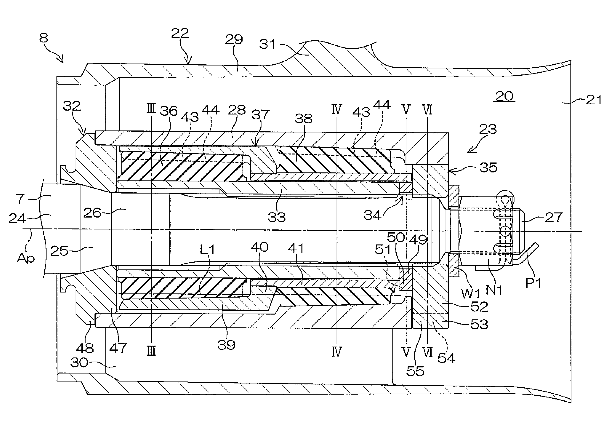
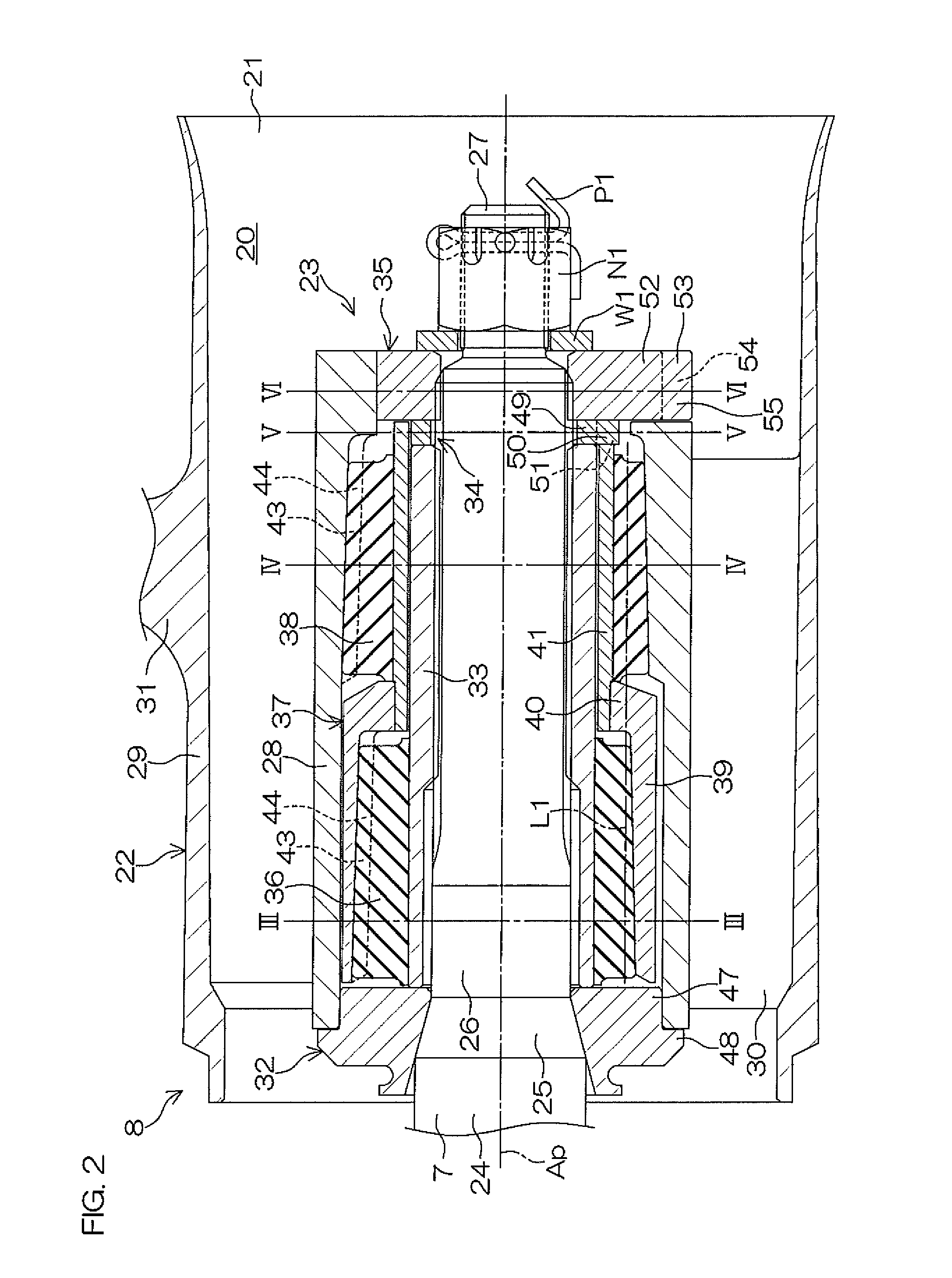
[0099]FIG. 8 is a sectional view of the propeller shaft 7 and a propeller 208 according to a second preferred embodiment of the present invention. A free state in which a torque is not applied to a damper unit 223 is illustrated in FIG. 8. In the following, the damper unit 223 in the free state shall be described unless noted otherwise. Also, in FIG. 8, component portions equivalent to respective portions shown in FIG. 1 to FIG. 7 described above shall be provided with the same reference symbols as in FIG. 1, etc., and description thereof shall be omitted.

[0100]The propeller 208 according to the second preferred embodiment includes a cylindrical propeller member 222 that generates a thrust and the cylindrical damper unit 223 that is detachably mounted on the propeller member 222. The propeller 208 is detachably mounted on the rear end portion of the propeller shaft 7 by the washer W1 and the nut N1.

[0101]In addition to the inner cylinder 28, the outer cylinder 29, the plurality of r...

third preferred embodiment

[0116]FIG. 9 is a sectional view of the propeller shaft 7 and a propeller 308 according to a third preferred embodiment of the present invention. A free state in which a torque is not applied to a damper unit 323 is illustrated in FIG. 9. In the following, the damper unit 323 in the free state shall be described unless noted otherwise. Also, in FIG. 9, component portions equivalent to respective portions shown in FIG. 1 to FIG. 8 described above shall be provided with the same reference symbols as in FIG. 1, etc., and description thereof shall be omitted.

[0117]The propeller 308 according to the third preferred embodiment includes the propeller member 22 according to the first preferred embodiment and the cylindrical damper unit 323 that is detachably mounted on the propeller member 22. The propeller 308 is detachably mounted on the rear end portion of the propeller shaft 7 by the washer W1 and the nut N1.

[0118]The damper unit 323 is disposed on the propeller axis Ap. The damper unit...

fourth preferred embodiment

[0125]FIG. 10 is a sectional view of the propeller shaft 7 and a propeller 408 according to a fourth preferred embodiment of the present invention. A free state in which a torque is not applied to a damper unit 423 is illustrated in FIG. 10. In the following, the damper unit 423 in the free state shall be described unless noted otherwise. Also, in FIG. 10, component portions equivalent to respective portions shown in FIG. 1 to FIG. 9 described above shall be provided with the same reference symbols as in FIG. 1, etc., and description thereof shall be omitted.

[0126]The propeller 408 according to the fourth preferred embodiment includes the propeller member 222 according to the second preferred embodiment and the cylindrical damper unit 423 that is detachably mounted on the propeller member 222. The propeller 408 is detachably mounted on the rear end portion of the propeller shaft 7 by the washer W1 and the nut N1.

[0127]The damper unit 423 is disposed on the propeller axis Ap. The dam...


PUM


Abstract

A damper unit includes a first damper arranged to transmit a torque around a rotation axis transmitted from an input member side to an output member side, an intermediate member arranged to transmit a torque around the rotation axis transmitted from the first damper to the output member side, and a second damper arranged to transmit a torque around the rotation axis transmitted from the intermediate member to the output member side, wherein at least a portion of the second damper is disposed on a straight line that passes through the first damper and is parallel or substantially parallel to the rotation axis.

Description

BACKGROUND OF THE INVENTION[0001]1. Field of the Invention[0002]The present invention relates to a damper unit for a vessel propulsion apparatus, a propeller for a vessel propulsion apparatus including the damper unit, and a vessel propulsion apparatus including the damper unit.[0003]2. Description of the Related Art[0004]A propeller for a vessel propulsion apparatus is mounted on a propeller shaft via a propeller damper (damper unit). The damper unit transmits a torque between the propeller and the propeller shaft and absorbs a vibration between the propeller and the propeller shaft. An impact (shift shock) accompanying engagement / disengagement of a dog clutch and an impact accompanying collision of the propeller and an underwater obstacle are absorbed by the damper unit. The damper unit thus contributes to the protection of parts, reduction of impact noise, and improvement of maneuverability.[0005]A damper unit according to U.S. Patent Application Publication No. 2011 / 0212657 A1 i...

Claims


Application Information

Patent Timeline
Patent Type & Authority Patents(United States)
IPC IPC(8): B63H23/34B63H21/30B63H1/15F16F7/10F16F15/126B63H21/34
CPCF16F7/10B63H1/15B63H21/305B63H21/34F16F15/126B63H2023/342Y10T74/2121B63H23/34
Inventor NAKAMURA, DAISUKEMASUDA, TIHARUKUROKI, YOUHEI
Owner YAMAHA MOTOR CO LTD
Why Eureka
Try Eureka