Fixed-type constant-velocity universal joint

Active Publication Date: 2006-09-28
NTN CORP
View PDF13 Cites 14 Cited by
  • Summary
  • Abstract
  • Description
  • Claims
  • Application Information

AI Technical Summary

Benefits of technology

[0127] In the fixed-type constant velocity universal joints described in (1) through (7) above, the track grooves of the outer and inner joint members are preferably finished by cold forging. The

Problems solved by technology

Although the fixed-type constant velocity universal joints described in the above-mentioned publications each have outer and inner joint members featuring tapered track grooves that permit a larger operating angle of the joint, the current trend toward lightweight and compac

Method used


Image

  • Fixed-type constant-velocity universal joint
  • Fixed-type constant-velocity universal joint
  • Fixed-type constant-velocity universal joint

Examples


Embodiment Construction

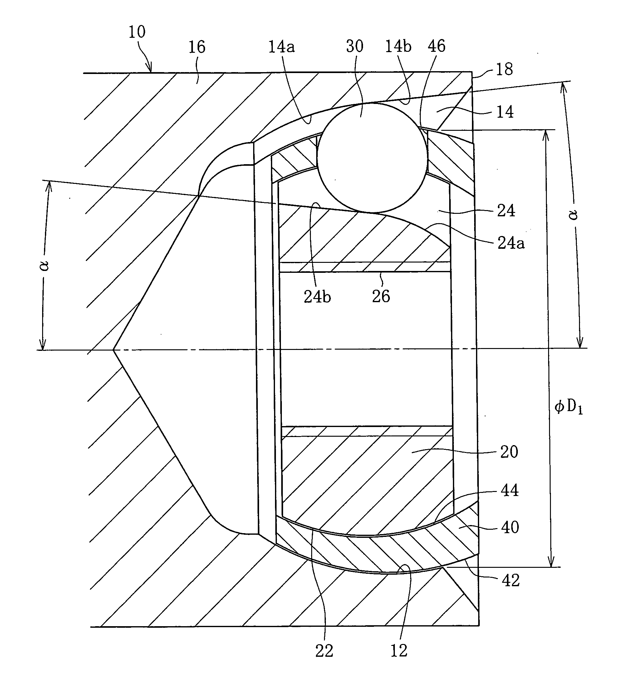
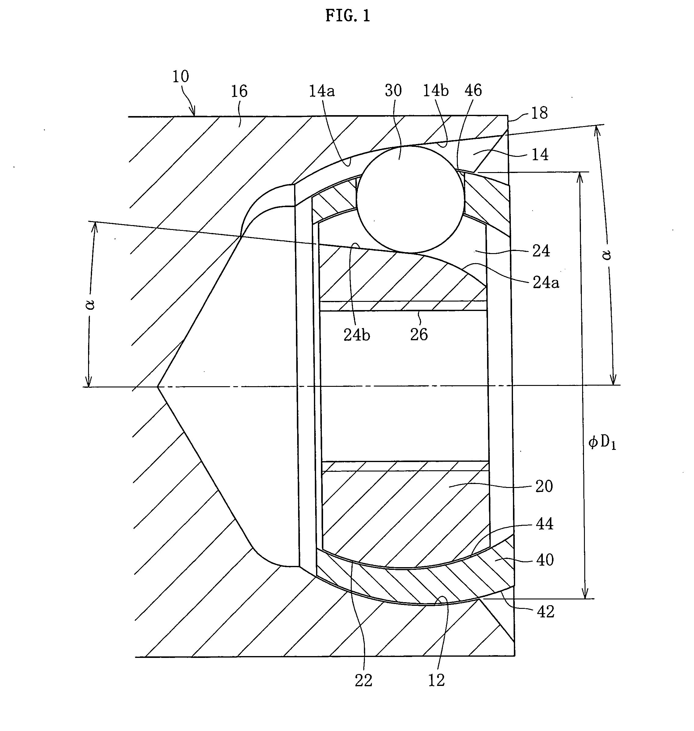
[0151] Referring to FIG. 1, a fixed-type constant velocity universal joint comprises an outer ring 10, an inner ring 20, a ball 30 and a cage 20. The fixed-type constant velocity universal joint connects two shafts to be connected. For example, a driven shaft (not shown) is connected to the outer ring 10, to which a driving shaft (not shown) is connected so that the torque is transmitted at constant velocity from the driving shaft to the driven shaft when the two shafts are at an angle to each other. FIG. 1 shows the state in which the operating angle θ that the rotation axis X of the outer ring 10 makes with the rotation axis Y of the inner ring 20 is 0°, whereas FIG. 1 shows the state in which the operating angle θ is at its maximum.

[0152] The outer ring 10 to serve as the outer joint member consists of a mouth portion 16 and a stem portion (not shown) that is coupled to the driving shaft in a torque-transmitting manner. The mouth portion 16 is essentially a cup with an open end ...


PUM


Abstract

Internal dimensions for fixed-type constant velocity universal joints are defined to optimize the geometry of the components of the joints and to readily achieve a larger operating angle of the joints. In the joint, the track grooves of an outer ring and an inner ring are tapered by an angle not exceeding 12°. The ratio (f/PCR) of the cage offset amount f to PCR is greater than 0 and smaller than or equal to 0.12. The ratio (Do/d) of the cage outer diameter (Do) to the ball diameter (d), the ratio (t/d) of the cage wall thickness (t) to the ball diameter (d), and the ratio (w/d) of the cage width (w) to the ball diameter (d) are such that 3.9≦Do/d≦4.1, 0.31≦t/d≦0.34, and 1.8≦w/d≦2.0, respectively. The end of the spherical outer surface of the cage adjacent to the open end is axially extended, and the end of the spherical inner surface of the cage adjacent to the open end is tapered so that the tapered surface has an increasing diameter toward the end of the spherical outer surface adjacent to the open end. Part of the spherical outer surface of the cage is cut on the open end side of pockets, and the outer diameter of the cage across the two opposing planer cut faces is smaller than the spigot diameter of the outer ring.

Description

BACKGROUND OF THE INVENTION [0001] 1. Field of the Invention [0002] The present invention relates to fixed-type constant velocity universal joints. Constant velocity universal joints are used in the power transmission of automobiles and various industrial machines and transmit torque from a driving shaft to a driven shaft at a constant angular velocity. Two types of constant velocity universal joints are known: fixed-type, which permits only angular displacement, and slidable-type, which permits both angular and axial displacement. [0003] 2. Description of the Related Art [0004] A typical fixed-type constant velocity universal joint includes the following components: an outer joint member that is connected to a driving or driven shaft in a torque-transmitting manner; an inner joint member that is connected to the driven or driving shaft in a torque-transmitting manner; a plurality of balls placed between the outer and inner joint members to transmit torque; and a cage that holds the...

Claims


Application Information

Patent Timeline
IPC IPC(8): F16D3/34
CPCF16D3/2237F16D2003/22303Y10S464/906F16D3/223
Inventor HOSHINO, MANABUNAKAGAWA, TOHRUTONE, HIROSHISUGANUMA, WASABURO
Owner NTN CORP
Why Eureka
Try Eureka