Eureka AIR delivers breakthrough ideas for toughest innovation challenges, trusted by R&D personnel around the world.

Unit that comprises a winding ratchet that is attached to a barrel arbor and barrel arbor for this unit

a technology of winding ratchets and barrel arbors, which is applied in the direction of timers, electromechanical clocks, time indications, etc., can solve the problems of increasing the weight reducing therefore the amount of space it requires, and the diameter of the barrel cage, so as to reduce the diameter of the barrel arbor, reduce the minimum space requirement of the barrel, and reduce the effect of the barrel arbor

Active Publication Date: 2010-06-17
DURAFOURG FRANCOIS
View PDF7 Cites 15 Cited by
  • Summary
  • Abstract
  • Description
  • Claims
  • Application Information

AI Technical Summary

Benefits of technology

"The invention is a device for attachment of a winding ratchet to a barrel shaft that allows for a smaller barrel arbor diameter, more operating space, and a reduction in weight. The device includes a ratchet with off-centered tapping and an attachment washer with off-centered piercing that securely attaches the ratchet to the barrel arbor. The angular positions of the piercings are different from the angle of the ratchet tappings. The barrel arbor also includes a pivot and a driving element that form a groove for attachment of the ratchet. The invention allows for a compact and lightweight barrel arbor design."

Problems solved by technology

This method is particularly aesthetic but involves the drawback of requiring a large-diameter barrel arbor that uselessly occupies a large volume of the inside space of the barrel cage, which makes it necessary to limit the length and the number of coils of the barrel spring for a barrel cage of a given diameter.
The result is a reduction in the operating reserve or an increase in the diameter of the barrel cage and therefore the amount of space it requires.
The result is also a weight increase of the barrel arbor.

Method used


Image

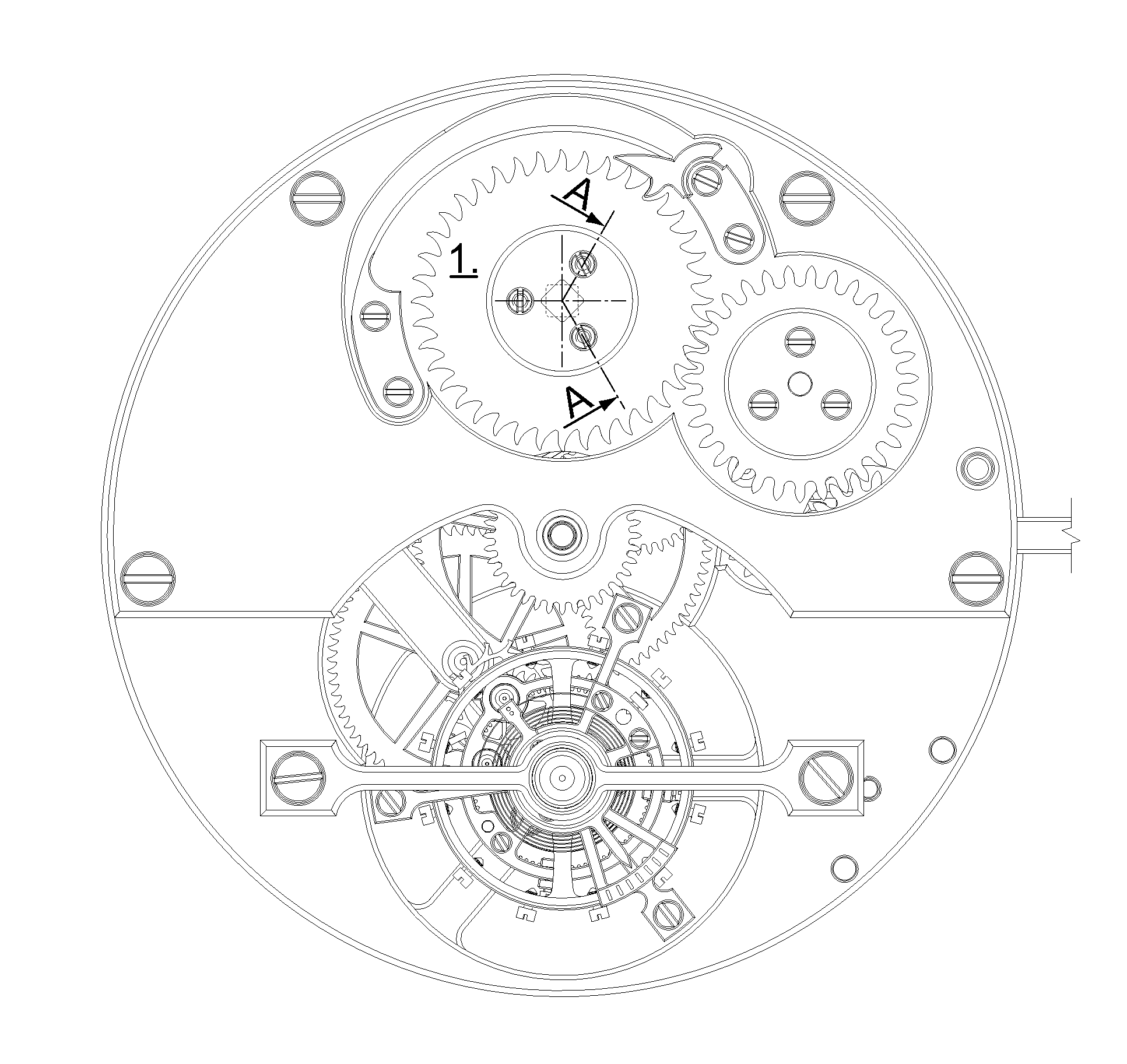
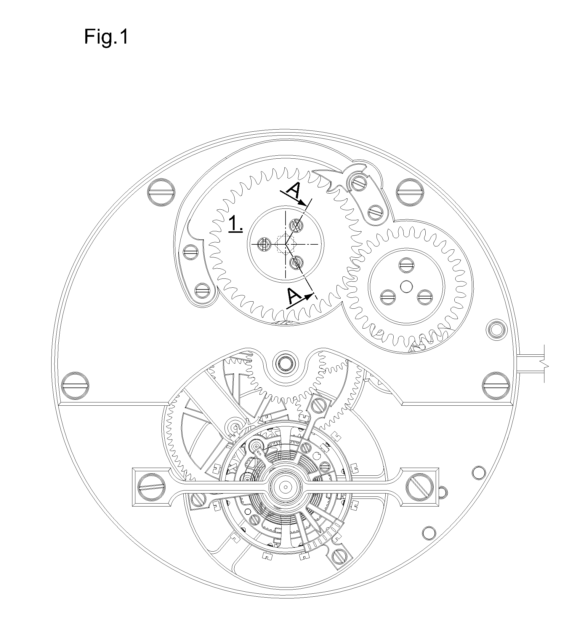
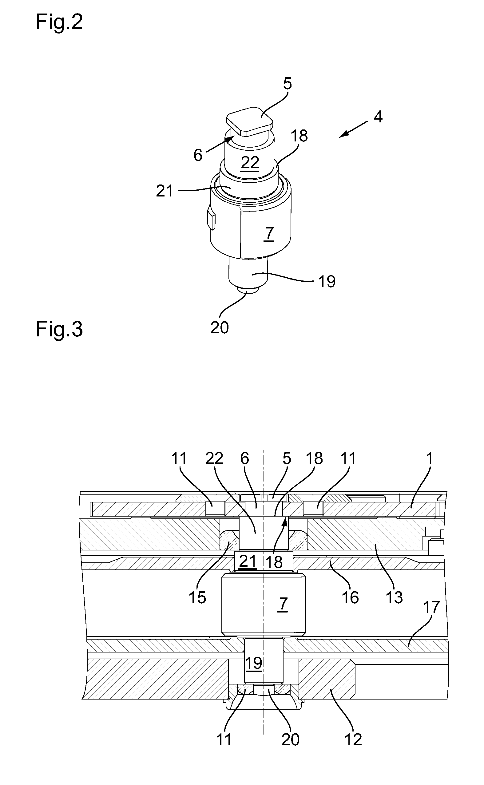
  • Unit that comprises a winding ratchet that is attached to a barrel arbor and barrel arbor for this unit
  • Unit that comprises a winding ratchet that is attached to a barrel arbor and barrel arbor for this unit
  • Unit that comprises a winding ratchet that is attached to a barrel arbor and barrel arbor for this unit

Examples


Embodiment Construction

[0014]As depicted in FIG. 6, the barrel ratchet a, driven by a square b, forming one end of the barrel arbor c, is screwed in—using screw d—directly into the terminal surface of the barrel arbor c that is pivoted between the platen d and the barrel bridge e. This type of attachment is generally used in the top-quality clock movements where the winding ratchet is visible. This attachment, with its three screws offset by 120°, is very aesthetic and pleasing to users. In contrast, this attachment mode requires a large diameter of the barrel arbor, clearly larger than ten times the thickness of the barrel spring that is the standard, and therefore unduly reduces the volume of the barrel cage and the operating reserve of the movement, whereby the spring has fewer coils for a given space requirement of the barrel.

[0015]The device for attaching a winding ratchet to a barrel arbor, according to the invention, makes it possible to produce a unit that has the same aesthetics as those of the p...


PUM


Abstract

A unit is formed by a winding ratchet (1) and a barrel arbor (4) having an end which includes a non-circular driving formation (5) and a groove (6) adjacent thereto that defines a small-section portion whose shape and dimensions are such that they extend into the section of the driving formation, whereby a shoulder (18) of the barrel arbor limits the height of the groove. The ratchet includes a central opening (2) corresponding to the driving formation and at least one off-centered tapping (3) relative to the ratchet. It includes an attachment washer (8) having a central passage (9) corresponding to the driving formation and engaged therewith in an assembled position, and at least one off-centered piercing (10), at least one screw for screwing the attachment washer onto the ratchet in a position angularly offset so that in this assembled position, the central opening is not aligned with the central passage.

Description

FIELD OF THE INVENTION[0001]This invention has as its object a unit that comprises a winding ratchet that is attached to a barrel arbor, as well as a barrel arbor that is designed to be part of a timepiece.BACKGROUND OF THE INVENTION[0002]In top-quality timepieces, in particular in those where all or part of the movement is made visible, the winding ratchet comprises a square drive opening in which the end square of the barrel arbor is housed. This winding ratchet is then screwed in using three screws, generally into the terminal surface of the barrel arbor as it is depicted in FIG. 6.[0003]This method is particularly aesthetic but involves the drawback of requiring a large-diameter barrel arbor that uselessly occupies a large volume of the inside space of the barrel cage, which makes it necessary to limit the length and the number of coils of the barrel spring for a barrel cage of a given diameter. The result is a reduction in the operating reserve or an increase in the diameter of...

Claims


Application Information

Patent Timeline
Patent Type & Authority Applications(United States)
IPC IPC(8): G04B3/00
CPCG04B1/16
Inventor REYNARD, BERANGER
Owner DURAFOURG FRANCOIS
Why Eureka
Eureka Blog
Learn More