Cutting tool for a strap

a strap and cutting tool technology, applied in the field of strap cutting tools, can solve problems such as unergonomically optimal design, and achieve the effect of preventing recoil

Inactive Publication Date: 2008-09-09
SIGNODE IND GRP
View PDF23 Cites 8 Cited by
  • Summary
  • Abstract
  • Description
  • Claims
  • Application Information

AI Technical Summary

Benefits of technology

[0009]The movable and fixed elements are operably connected at their respective pivot regions by a pivot pin. A cutter guard having a flange is disposed to overlie a portion of the fixed element anvil to provide an opening between the flange and the anvil to place the strap during a cutting operation. The guard holds the strap at the anvil to prevent recoil when the strap is cut.

Problems solved by technology

Although this type of cutter functions well, because of the open handles, it is not an ergonomically optimal design.

Method used


Image

  • Cutting tool for a strap
  • Cutting tool for a strap
  • Cutting tool for a strap

Examples


Embodiment Construction

[0024]While the present invention is susceptible of embodiment in various forms, there is shown in the drawings and will hereinafter be described a presently preferred embodiment with the understanding that the present disclosure is to be considered an exemplification of the invention and is not intended to limit the invention to the specific embodiment illustrated.

[0025]It should be understood that the title of this section of this specification, namely, “Detailed Description of the Invention”, relates to a requirement of the United States Patent Office, and does not imply, nor should be inferred to limit the subject matter disclosed herein.

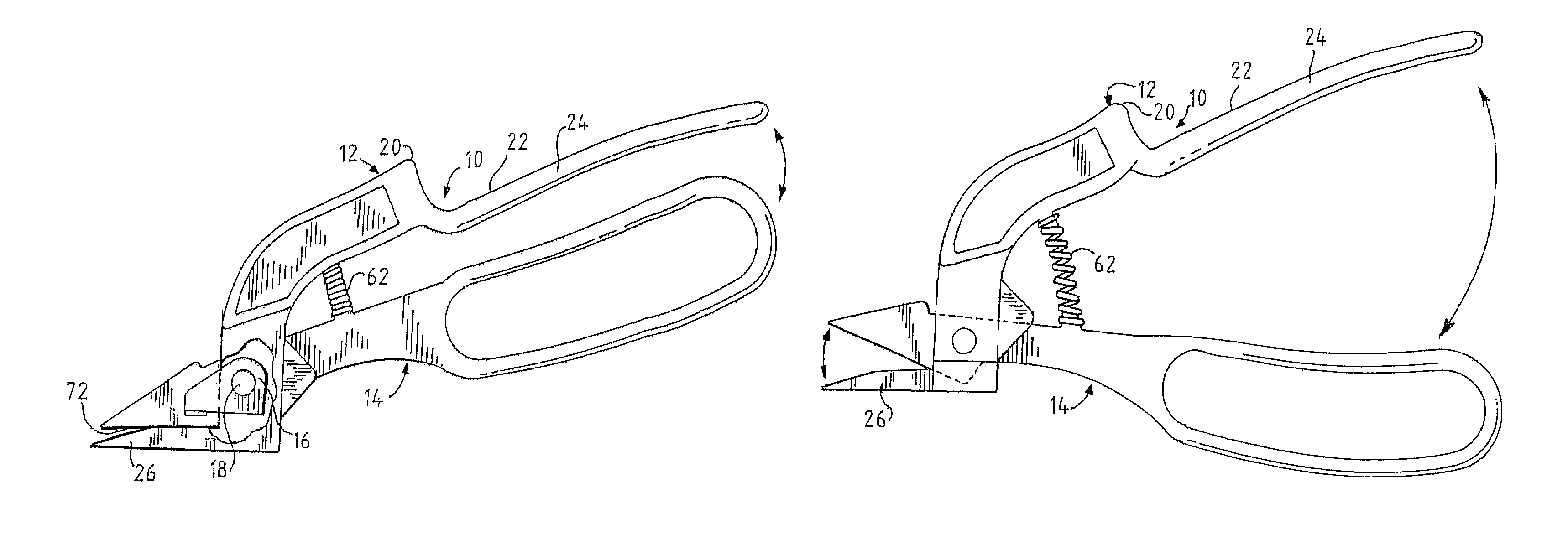
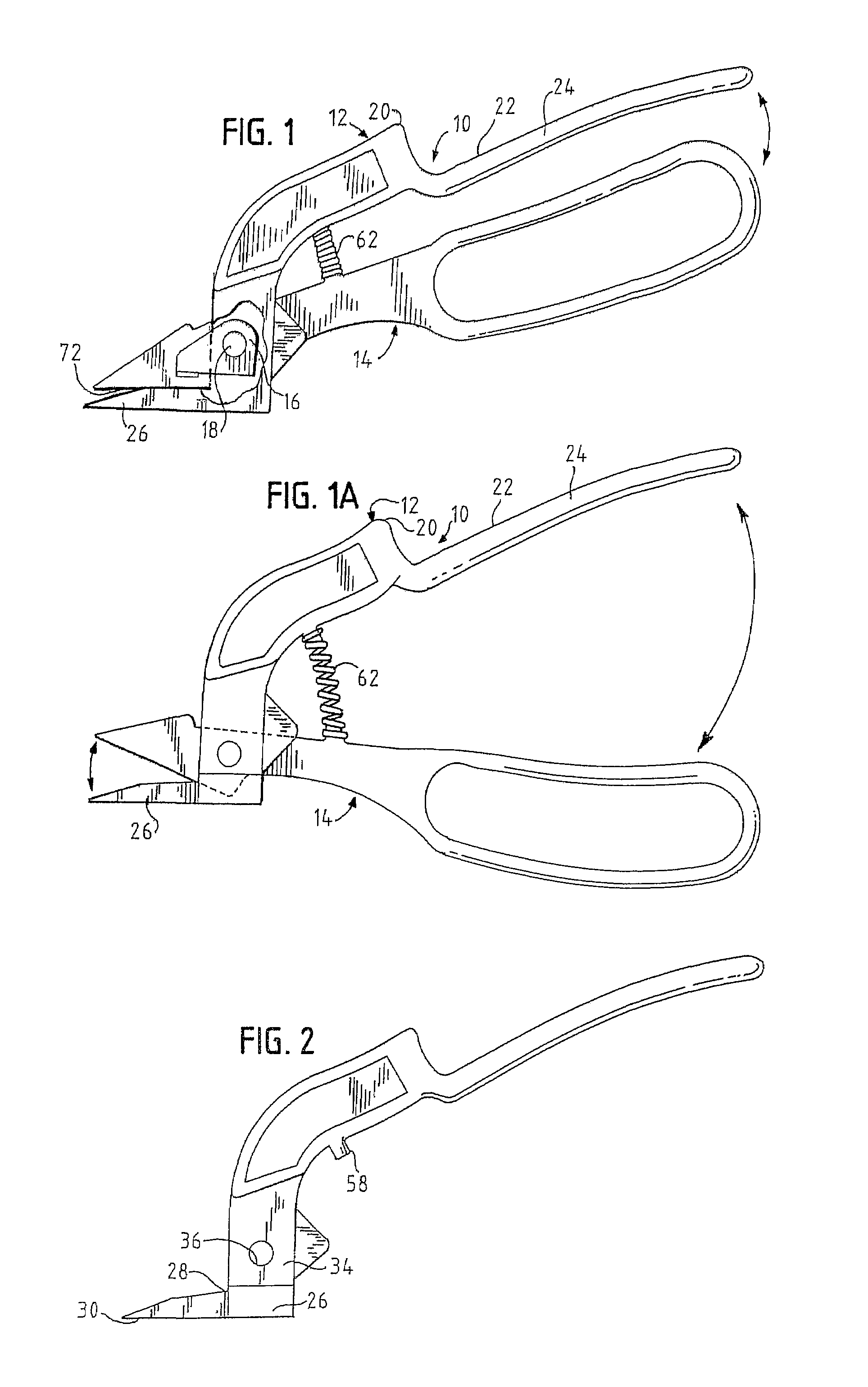
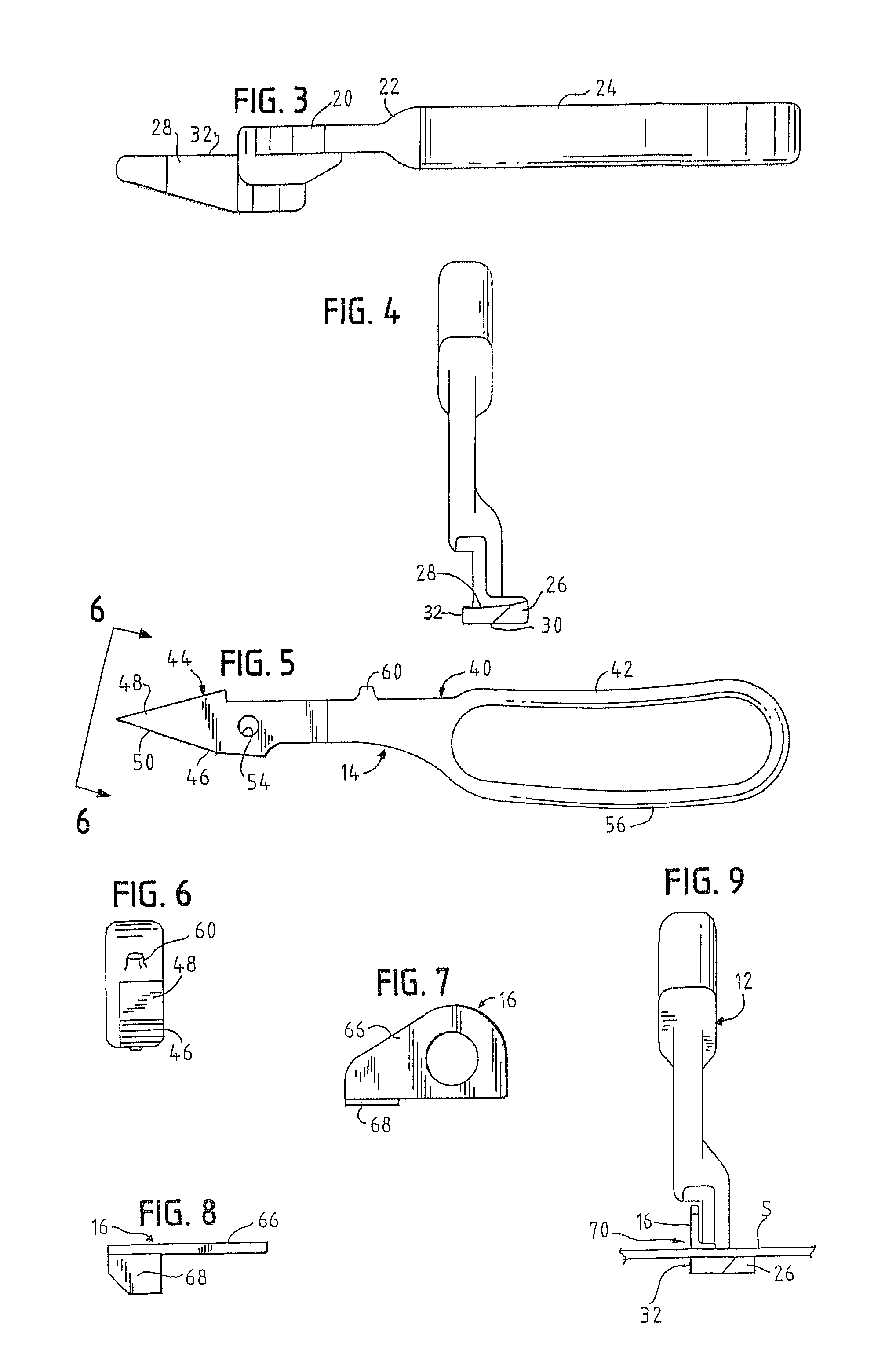
[0026]Referring now to the figures and in particular to FIG. 1, there is shown a cutting tool 10 for strap embodying the principles of the present invention. The tool 10 includes generally, a fixed element 12, a movable or pivoting element 14 and a cutter guard 16. The elements 12, 14 are mounted to one another, with the guard 16 between the ele...


PUM


Abstract

A cutting tool for strap includes a fixed element and a movable element pivotally operably connected to one another. The fixed element has a body, a grip extending from an end of the body and an anvil. The anvil has a cutting edge. A pivot region is defined between the cutting edge and the grip. The movable element has a body, an enclosed handle and a cutting head. The cutting head defines a cutting edge. A pivot region is defined between the cutting edge and the handle. The movable and fixed elements are operably connected at their respective pivot regions. A cutter guard having a flange is disposed to overlie a portion of the fixed element anvil to provide an opening between the flange and the anvil to place the strap during a cutting operation.

Description

BACKGROUND OF THE INVENTION[0001]The present invention relates to a cutting tool for strap. More particularly, the present invention relates to an enclosed handle tool for cutting metal and plastic strap.[0002]Strapping material is used in a wide variety of applications to secure or bundle loads. The strap material is typically metal or plastic and can be applied to the load using either a manual strapper or a powered (e.g., electric or pneumatic) strapper. The strap material is tensioned as it is secured to itself to bundle the load.[0003]In order to remove the tensioned strap, it is often necessary to cut or sever the strap. In that the strap can be quite strong, and under considerable tension, it is necessary that the cutter be strong and ergonomically designed.[0004]One known cutter includes a fixed handle with a foot for resting on the load and a movable handle that pivots about the fixed handle. A cutting blade is separate and apart from both the fixed and movable handles and ...

Claims


Application Information

Patent Timeline
Patent Type & Authority Patents(United States)
IPC IPC(8): B26B13/00
CPCB25G3/38
Inventor GARDNER, JOSEPH J.ROMETTY, JOHN A.
Owner SIGNODE IND GRP
Why Eureka
Try Eureka