
Multi-function egress path device

a multi-functional, egress path technology, applied in the direction of instruments, audible signalling systems, advertising, etc., can solve the problems of ineffective fire drill training of necessary occupants, ceiling may become obscured by smoke, etc., and achieve the effect of improving visibility

Active Publication Date: 2008-09-09
KONTOVICH MICHAEL STEPHEN
View PDF14 Cites 63 Cited by
  • Summary
  • Abstract
  • Description
  • Claims
  • Application Information

AI Technical Summary

Benefits of technology

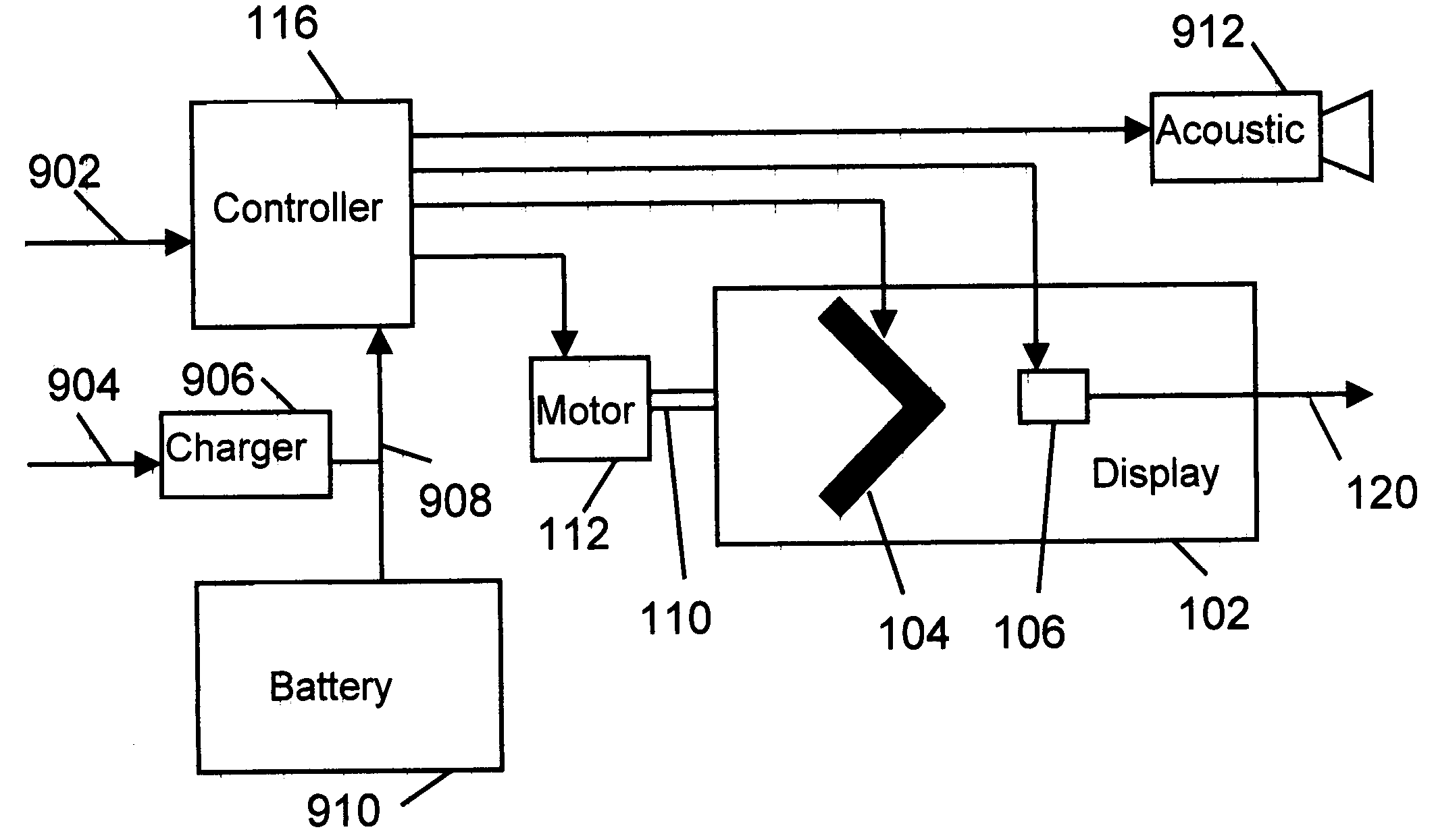
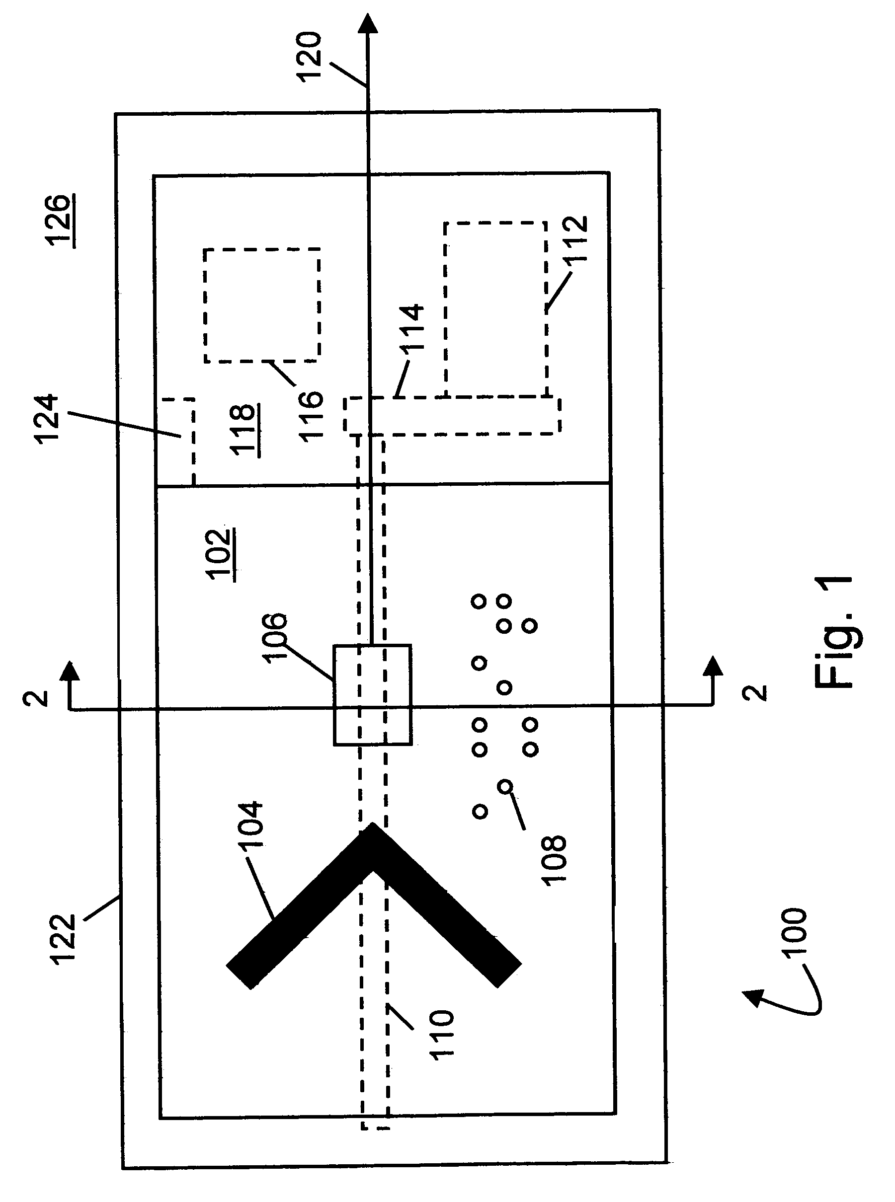
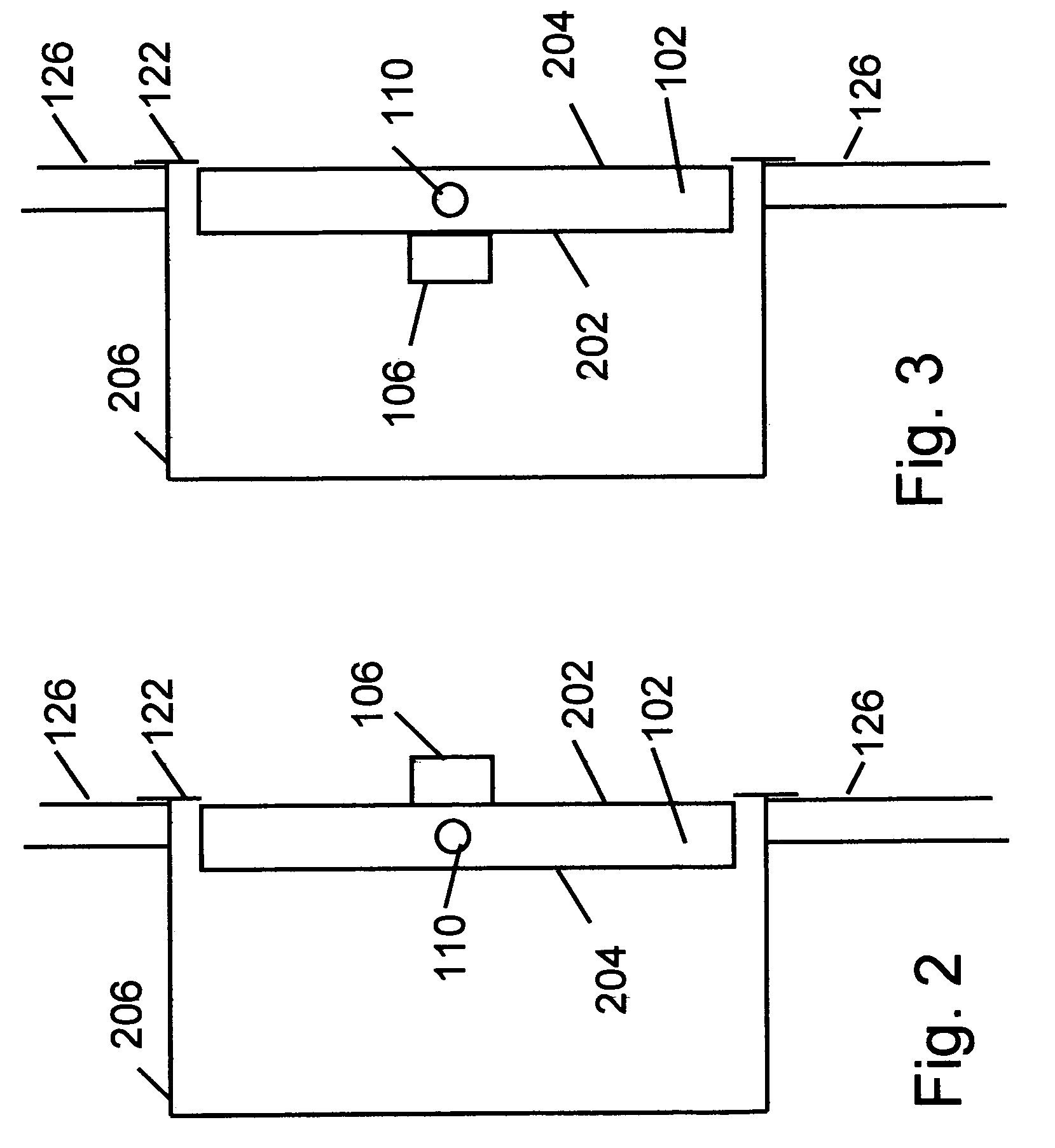
[0007]Briefly, the present invention is a system and method for providing emergency egress path indication by providing a path direction indicator that is hidden from view during normal operation and is exposed to view upon activation by an emergency signal. Upon being exposed to view the indicator may be lighted and may provide light to people seeking exit from the building. In one embodiment the indicator may include a laser pointer further indicating the direction of egress. Visible and Braille text may also be included on the face of the indicator. The indicator device may be located near floor level for better visibility in smoke environments. In the non-visible state, the indicator may present a rugged face to withstand accidental kicks and bumps as may be encountered when mounted near the floor. The indicator may be operated repetitively and nondestructively to allow inclusion of the indicator in fire and other emergency drills.

Problems solved by technology

Fire drills are not always effective in training the necessary occupants as many businesses for example are frequented by customers who are not likely to be present during a fire drill and who would often object to being bothered by a fire drill at a location they infrequently attend.
In a fire, however, the ceiling may become obscured by smoke

Method used


Image

  • Multi-function egress path device
  • Multi-function egress path device
  • Multi-function egress path device

Examples


Embodiment Construction

[0020]The present invention is a system and method for displaying egress direction information during an emergency. In accordance with the present invention, an egress information display device is installed preferentially near the floor of a room or hallway. The egress information device provides two display configurations. In a first configuration, the safe mode, the device hides the egress display signage and pointing devices and allows a pleasing architectural appearance. In a second configuration, the emergency configuration, the device displays the egress direction information. The second configuration may be entered upon receipt of an emergency signal as provided by, for example, a fire alarm system.

[0021]Being located near the floor is especially advantageous in a fire emergency because the smoke usually fills the room initially and most densely near the ceiling, potentially obscuring typical EXIT signs installed above the door. Egress signs located near the floor avoid the ...


PUM


Abstract

A system and method for providing emergency egress path indication by providing a path direction indicator that is hidden from view during normal operation and is exposed to view upon activation by an emergency signal. Upon being exposed to view the indicator may be lighted and may provide light to people seeking exit from the building. In one embodiment the indicator may include a laser pointer further indicating the direction of egress. Visible and Braille text may also be included on the face of the indicator. The indicator device may be located near floor level for better visibility in smoke environments. In the non-visible state, the indicator may present a rugged face to withstand accidental kicks and bumps as may be encountered when mounted near the floor. The indicator may be operated repetitively and nondestructively to allow inclusion of the indicator in fire and other emergency drills.

Description

REFERENCES[0001]This application claims the benefit of prior provisional application 60 / 614,434 filed Sep. 30, 2004 by Kontovich, which is incorporated herein by reference in its entirety.FIELD OF THE INVENTION[0002]The present invention pertains to the field of safety and emergency equipment and methods, more particularly to egress path indication devices and methods.BACKGROUND[0003]In an emergency, rapid and orderly evacuation of a building is essential for saving lives and minimizing damage by allowing firefighters full access without having to assist in evacuation or save trapped people who could not find their way out. Evacuation of a building is typically accomplished with reference to a predetermined evacuation plan. Maps are often provided showing the evacuation routes. Drills are often performed to inform occupants of the safety plan and work out any problems that arise. Essential to many plans is a system of lighted EXIT signs and other egress direction indicators. Many Fi...

Claims


Application Information

Patent Timeline
Patent Type & Authority Patents(United States)
IPC IPC(8): G08B3/00
CPCG08B7/066
Inventor KONTOVICH, MICHAEL STEPHEN
Owner KONTOVICH MICHAEL STEPHEN
Learn More