Time converter

a converter and time technology, applied in the field of time converters, can solve the problems of limited measurement accuracy, difficulty in realizing current sources that are constant, and the level of precision cannot be achieved

Active Publication Date: 2008-09-09
KEYSIGHT TECH
View PDF13 Cites 6 Cited by
  • Summary
  • Abstract
  • Description
  • Claims
  • Application Information

AI Technical Summary

Problems solved by technology

A limitation of this method is that the measurement accuracy is limited by the rate of the clock signal.
For a resolution of 10 picoseconds, for example, a 100 gigahertz clock signal is required, so that this level of precision can only be achieved with difficulty by this method.
An inconvenience of this method is the relatively great dead time associated to each measured event, so that this method is only applicable with difficulty to multiple and close pulses, such as for example signals generated by detectors of elementary particles (multi-hit events).
Another inconvenience of the above method is connected to the difficulty of realizing current sources that are constant and independent from the ramp's voltage.
Any difference of behavior between the two sources will induce conversion errors.
This method has however the disadvantage of a complex and delicate calibration.
Another inconvenience of the above method is connected to the difficulty of obtaining a voltage ramp that is exactly linear.
The non-linearity of the capacity and / or the non-constancy of the current source are the origin of conversion errors.
This method further requires a ramp calibration procedure due to the inevitable initial imprecision of the ramp capacity and current.

Method used


Image

  • Time converter
  • Time converter
  • Time converter

Examples


first embodiment

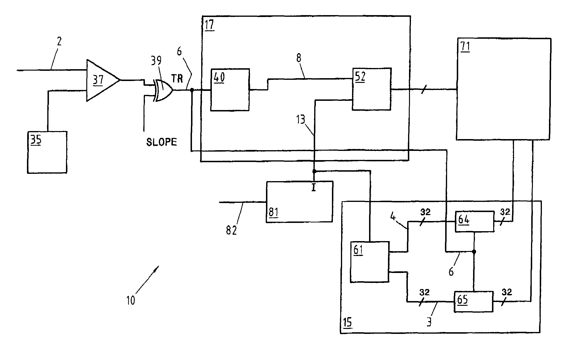
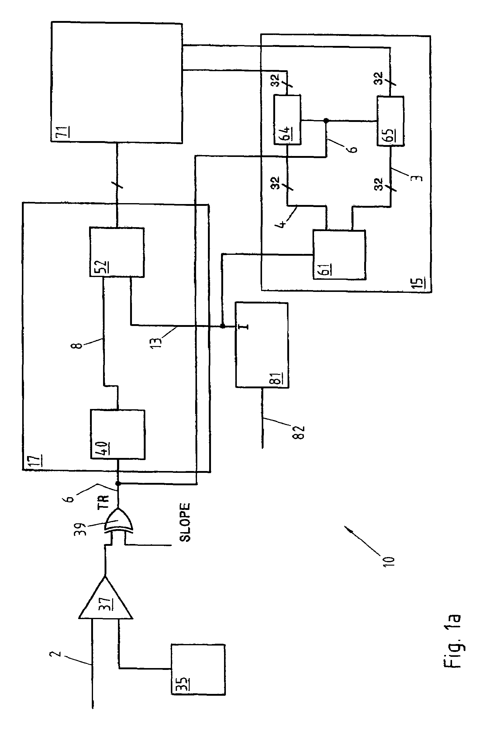
[0033]In the invention, described with reference to FIG. 1a, the generator 81 produces the sinusoidal signal 13 serving as time base for the converter 10. The sinusoid 13 is generated from an external clock signal 82, as indicated in FIG. 1a, or by a local time base generator, not represented. The frequency of the signal 13 is chosen according to the application and to the desired temporal resolution, within the limits imposed by the speed of the components used. In a typical case, a frequency of 100 MHz can be adopted although the present invention obviously also comprises devices with a higher or lower rate, as the case may be.

[0034]The digital trigger signal 6 is sent to a coarse measuring system 15, described further below in connection with FIGS. 1a and 2a. The coarse measuring circuit 15 comprises the real time counter 61 and the two registers 64, 65.

[0035]The real time counter 61 counts the periods of the sinusoidal signal 13 and is used to feed the two buses 3 and 4, whose c...

second embodiment

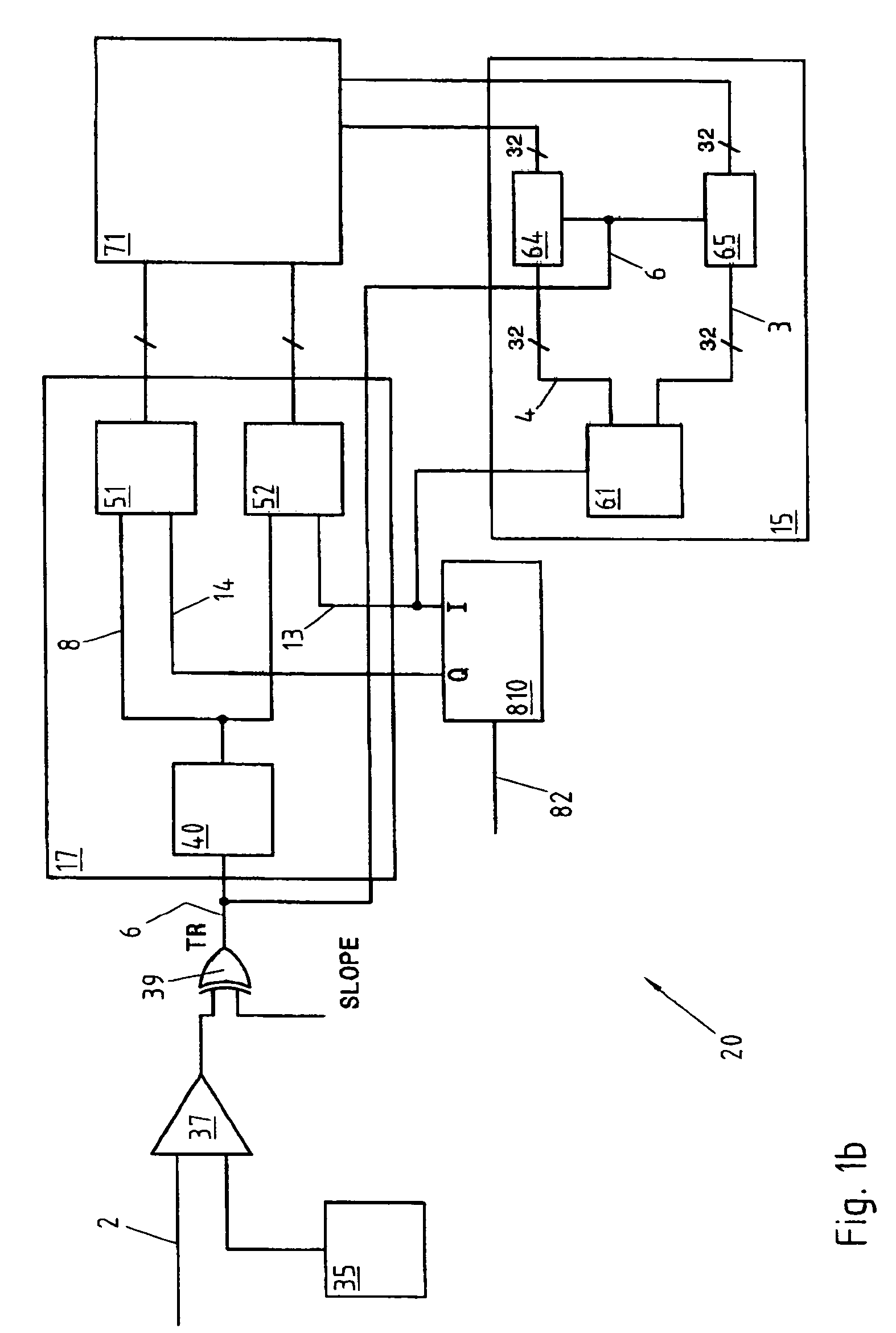
[0069]the present invention is now described with reference to FIG. 1b.

[0070]In this embodiment, the inventive time converter 20 comprises a generator 810 that produces the two sinusoidal signals 13 and 14 in quadrature that serve as time base for the converter 10. The first sinusoid 13 is also designated by I (In phase) and the second sinusoid 14 by Q (Quadrature). The signals 13 and 14 are generated from an external clock signal 82, as can be seen in FIG. 1, or by a local oscillator, not represented. The frequency of the signals 13 and 14 is chosen as a function of the resolution one wishes to achieve, as in the first embodiment already described.

[0071]The generator of the signals I and Q 810 is now described with reference to FIGS. 3 and 4. The reference signal 82 originating from outside or from a local oscillator is applied to the inputs of the two flip-flops 83, 84 to generate two square signals offset by 90°, whose frequency is half that of the signal 82. The two identical b...


PUM


Abstract

A digital time converter with an embodiment including a coarse measuring circuit and a fine measuring circuit. The fine measuring circuit allows an accurate determination of the temporal position of an event inside a period of the time base, by interpolation or averaging of sinusoids in quadrature, sampled coincidentally with a burst of impulses generated by the converter's triggering circuit.

Description

REFERENCE DATA[0001]This application claims priority of European patent application 2003EP-3103642 (as yet unpublished) filed on Oct. 1, 2003, the contents whereof are hereby incorporated by reference.TECHNICAL FIELD OF THE INVENTION[0002]The present invention concerns the field of time converters, and more precisely of time-digital-converters, designated TDC (Time-Digital-Converters).BACKGROUND OF THE INVENTION[0003]Time digital converters, or TDC, are used whenever one wishes to measure and encode accurately the temporal position of an event, or of a plurality of events, represented by electric pulses, relatively to a reference signal, defining the origin of the temporal scale.[0004]TDCs are used for example in the field of particle physics, to measure the transit time of the elementary particles produced during an interaction, in the different active zones of a segmented particle detector.[0005]TDCs also have applications in many other fields in which an accurate measurement of a...

Claims


Application Information

Patent Timeline
Patent Type & Authority Patents(United States)
IPC IPC(8): G04F8/00G04F1/00G04F10/00G04F10/06G04F10/04
CPCG04F10/04G04F10/00
Inventor BOLLI, JEAN-LUCGOUMAZ, JEAN-FRANCOIS
Owner KEYSIGHT TECH
Why Eureka
Try Eureka