
Radio apparatus and adaptive array processing method

a technology of array processing and radio apparatus, applied in the field of radio apparatus and adaptive array processing method, can solve the problems of insufficient number of reference signals included for each carrier, the inability to establish directivity of favorable accuracy, and the inability to combine the two schemes

Inactive Publication Date: 2008-09-09
SANYO ELECTRIC CO LTD +1
View PDF10 Cites 18 Cited by
  • Summary
  • Abstract
  • Description
  • Claims
  • Application Information

AI Technical Summary

Benefits of technology

[0249]As described above, usage of a configuration of an adaptive array base station of the present invention allows a multipath signal within a guard interval to be combined at the maximum ratio to maximize the reception sensitivity. Furthermore, the antenna degree of freedom is not consumed when a multipath signal within the guard interval is combined. The interference suppression performance can be maintained.
[0250]According to a radio apparatus and adaptive array processing method of the present invention described above, the reception sensitivity can be improved even in the case of adaptive array reception for the OFDM transmission scheme. The present invention is particularly useful in an adaptive array base station.

Problems solved by technology

However, the mere combination of the two schemes will pose problems set forth below.
Therefore, the number of symbols of a reference signal included for each carrier is often not sufficient for the signals transmitted through the OFDM scheme.
There was a problem that directivity of favorable accuracy could not be established.
This will lead to degradation in reception sensitivity
Summarizing, there is a problem that is difficult to ensure a sufficient reference signal required for directional control of high accuracy in the configuration of operating an adaptive array differing for each carrier as shown in FIG. 17.
There is also a problem that the reception sensitivity is degraded since multipath signals within the guard interval cannot be combined in maximum ratio.
In such a case, there will be a problem that combination at the maximum ratio is not conducted when viewed over the entire carrier.
This operation is disadvantages in that, although the short delayed signal per se is a desired wave whose property may be improved if used effectively, such a short delayed signal will be removed by the adaptive array processing, resulting in the problem of degradation in communication quality.

Method used


Image

  • Radio apparatus and adaptive array processing method
  • Radio apparatus and adaptive array processing method
  • Radio apparatus and adaptive array processing method

Examples


first embodiment

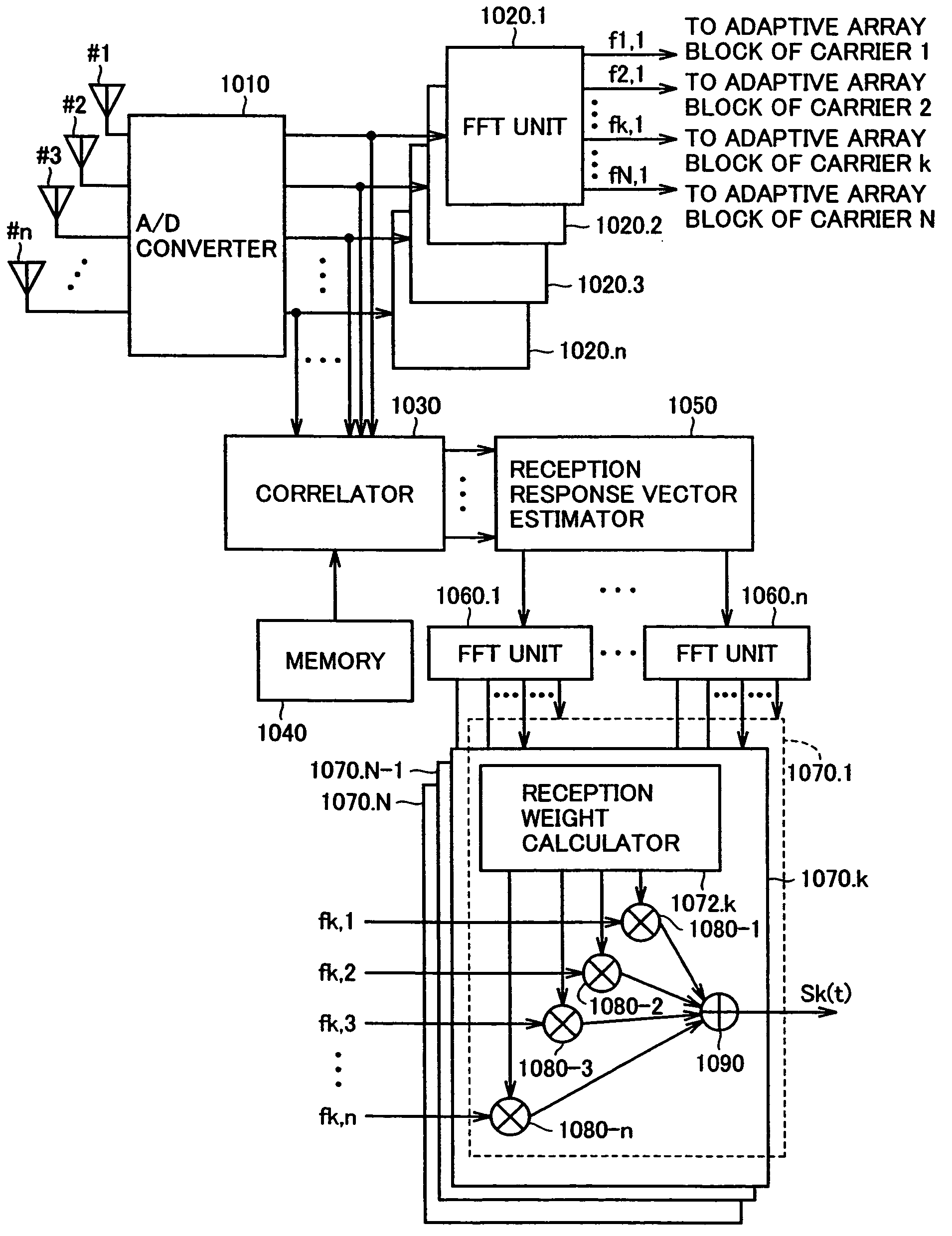
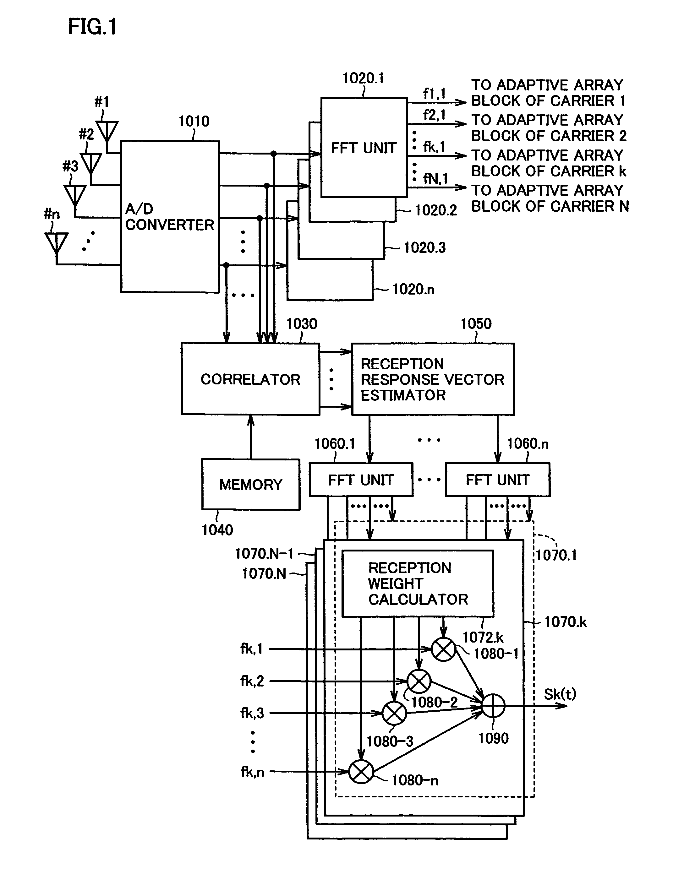
[0133]FIG. 1 is a schematic block diagram to describe a configuration of adaptive array base station 1000 according to an embodiment of the present invention. Adaptive array base station 1000 of the present invention transmits and receives a signal having directivity by adaptive array processing with respect to a mobile station such as a user's terminal. It is to be noted that adaptive array base station 1000 can also transmit and receive a signal with respect to a mobile station through the spatial division multiple scheme as will be described afterwards.

[0134]Referring to FIG. 1, adaptive array base station 1000 includes an array antenna formed of n (n: natural number) antennas, an A / D converter 1010 to conduct detection and analog-digital conversion on signals received from array antennas #1-#n, FFT units 1020.1-1020.n provided for respective n antennas, receiving outputs from A / D converter 1010 to separate and extract signals for respective carriers for corresponding antennas, a...

second embodiment

[0231]In the first embodiment, a complex response of a desired signal and a complex response of an interfering signal were obtained in accordance with a method described with reference to equations (22)-(26) as an operation of reception response vector estimator 1050.

[0232]In the case where there is no overlapping between the reference signal section of a desired signal and the reference signal section of an interfering signal, the method described in accordance with equations (22)-(26) does not exactly apply.

[0233]The second embodiment is directed to a method of obtaining a complex response of a desired signal and a complex response of an interference signal applicable even in such a case.

[0234](Estimation of Response of Desired Signal)

[0235]To obtain the complex response of a desired signal, an evaluation function J2 applied by the following equation (35) is employed. Unless stated otherwise, the notations of the following equations are similar to those of equations (22)-(26).

[023...


PUM


Abstract

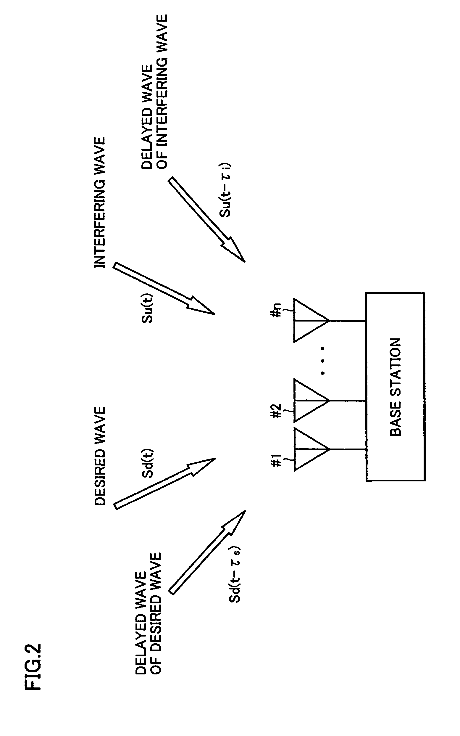
A correlator detects arriving timings of a desired wave and an interfering wave from a signal transmitted by the OFDM scheme. A reception response vector estimator estimates a first response vector for a signal arriving within a guard interval section from the head arriving wave and a second response vector for a signal arriving after the guard interval section from the head arriving wave out of the desired wave, and also a third response vector for a signal arriving within the guard interval section from the head arriving wave and a fourth response vector for a signal arriving after the guard interval section from the head arriving wave out of the interfering wave. An adaptive array block provides a weight vector based on a result of Fourier transform on the first to fourth response vectors.

Description

TECHNICAL FIELD[0001]The present invention relates to a configuration of a radio apparatus employed in a base station and an adaptive array processing method in radio communication mainly for a mobile such as a cellular phone.BACKGROUND ART[0002]In the field of mobile communication systems (for example, personal handyphone system: PHS) evolving rapidly these few years, an adaptive array base station is adapted to practical usage. The adaptive array base station separates and extracts a signal of the desired wave by applying the well known adaptive array processing on the reception signal of an array antenna composed of a plurality of antennas in order to suppress the effect of interfering waves to obtain favorable communication quality.[0003]Furthermore, by employing such an adaptive array base station, a PDMA (Path Division Multiple Access) system can be realized. The PDMA system allows mobile terminal devices of a plurality of users to be subjected to path division multiple access...

Claims


Application Information

Patent Timeline
IPC IPC(8): H04J11/00G01S3/16H04B1/00H04B1/10H04B7/00H04B7/08H04B7/26H04L1/06H04L25/02H04L27/26
CPCH04B7/0615H04B7/0848H04L25/022H04L25/0228H04L27/2647H04L25/0204H04B7/0854H04B7/0857H04B7/0897H04L27/26
Inventor OGAWA, YASUTAKAOHGANE, TAKEODOI, YOSHIHARU
Owner SANYO ELECTRIC CO LTD
Learn More