
Method for removing the coupling and correlation of antennas, and wireless device having the function of removing the coupling and correlation of antennas

a wireless device and antenna technology, applied in the field of broadcast receiving devices, can solve the problems of large size, unsuitable for portable size, and devices using noise cancellation and diversity techniques, and achieve the effect of maximizing the receiving sensitivity

Active Publication Date: 2010-07-29
PANASONIC INTELLECTUAL PROPERTY CORP OF AMERICA
View PDF8 Cites 5 Cited by
  • Summary
  • Abstract
  • Description
  • Claims
  • Application Information

AI Technical Summary

Benefits of technology

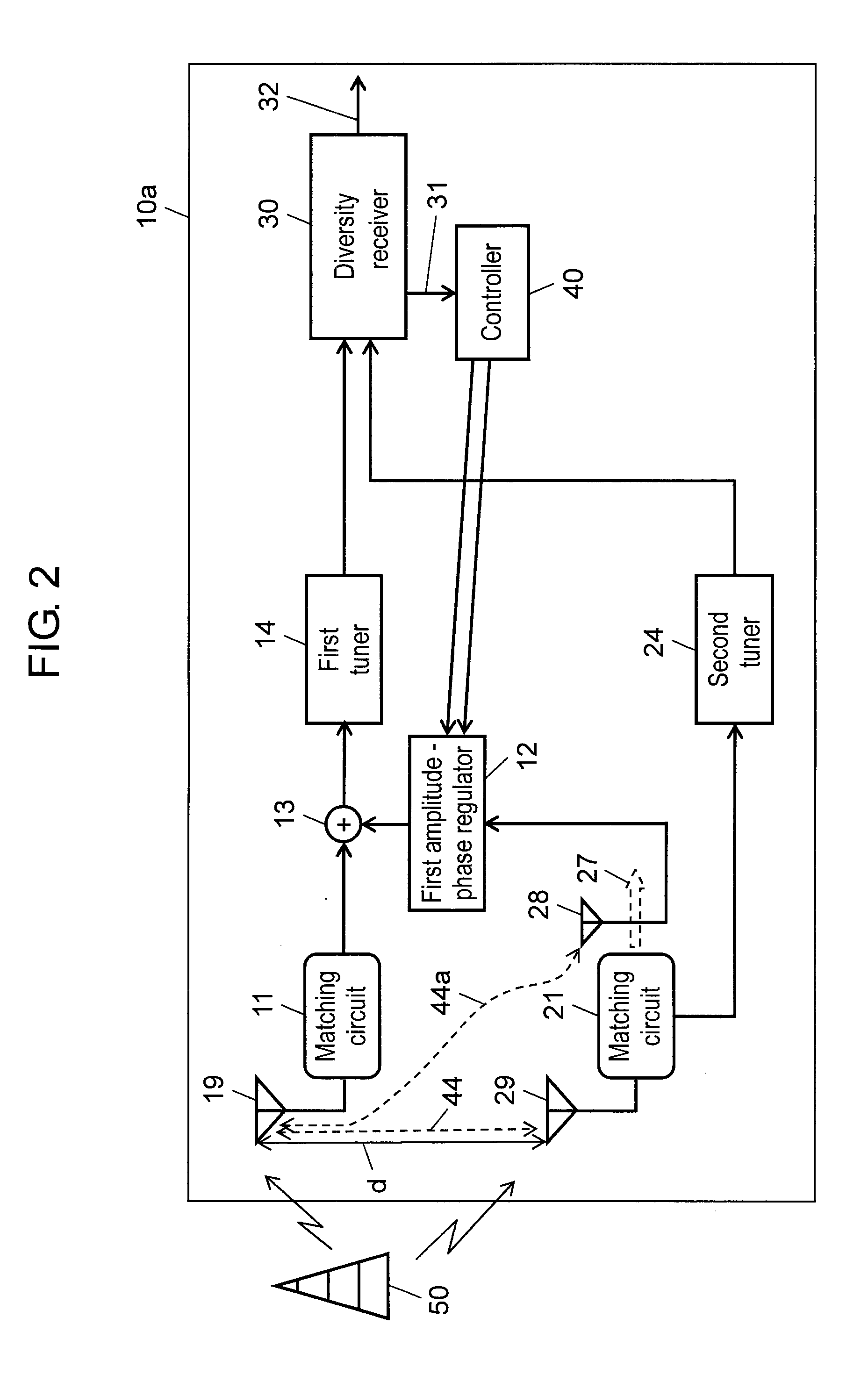
[0016]An amplitude-phase regulation step allows the first amplitude-phase regulator to control the amplitude and phase of the pickup signal outputted from the first sensor.
[0022]A control step allows the controller to control the amplitude and phase of the first pickup signal according to the reception quality signal outputted from the diversity receiver so as to control the first amplitude-phase regulator for optimizing the reception quality signal.
[0026]With this structure, the coupled component, which is induced from the first antenna to the second antenna, is cancelled together with the noise component, thus mainly cancelling the largest cause of desensitization. This results in the maximization of the receiving sensitivity.

Problems solved by technology

These conventional devices using noise-cancelling and diversity techniques, however, are large in size and usually mounted on vehicles such as cars, thus being not suitable to be reduced to a portable size.
When reduced to a portable size, these devices cause a decrease in the receiving sensitivity due to the coupling between diversity antennas and also cause gain degradation due to the diversity correlation.
This makes it impossible for these devices to provide desired high-sensitivity reception.
When a device includes a plurality of noise sources, such as a signal processing circuit, a clock part, a liquid crystal display driving part, bus lines in various types of memories, and a DC-DC converter, it is difficult to identify the noise component causing the gain degradation in each channel.
Therefore, cancelling the noise component causing the gain degradation requires picking up all the related noise components.
Thus, this technique does not reduce desensitization caused by their noises.
When the technique is applied to a small-sized device, the device causes a decrease in the receiving sensitivity due to the coupling between diversity antennas and also causes gain degradation due to the diversity correlation.
Thus, the problem of not having the ability to provide high-sensitivity reception remains unsolved.

Method used


Image

  • Method for removing the coupling and correlation of antennas, and wireless device having the function of removing the coupling and correlation of antennas
  • Method for removing the coupling and correlation of antennas, and wireless device having the function of removing the coupling and correlation of antennas
  • Method for removing the coupling and correlation of antennas, and wireless device having the function of removing the coupling and correlation of antennas

Examples


first exemplary embodiment

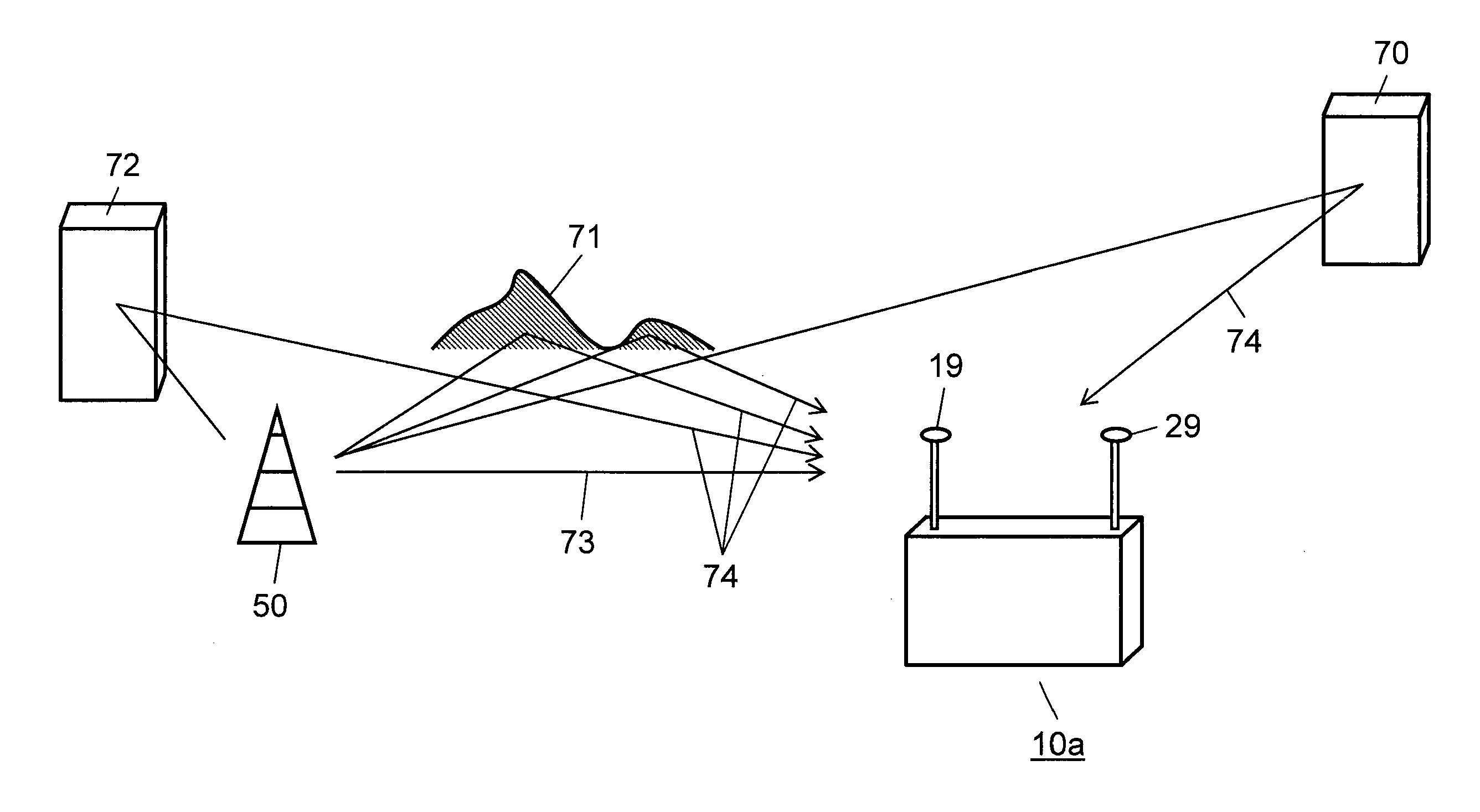
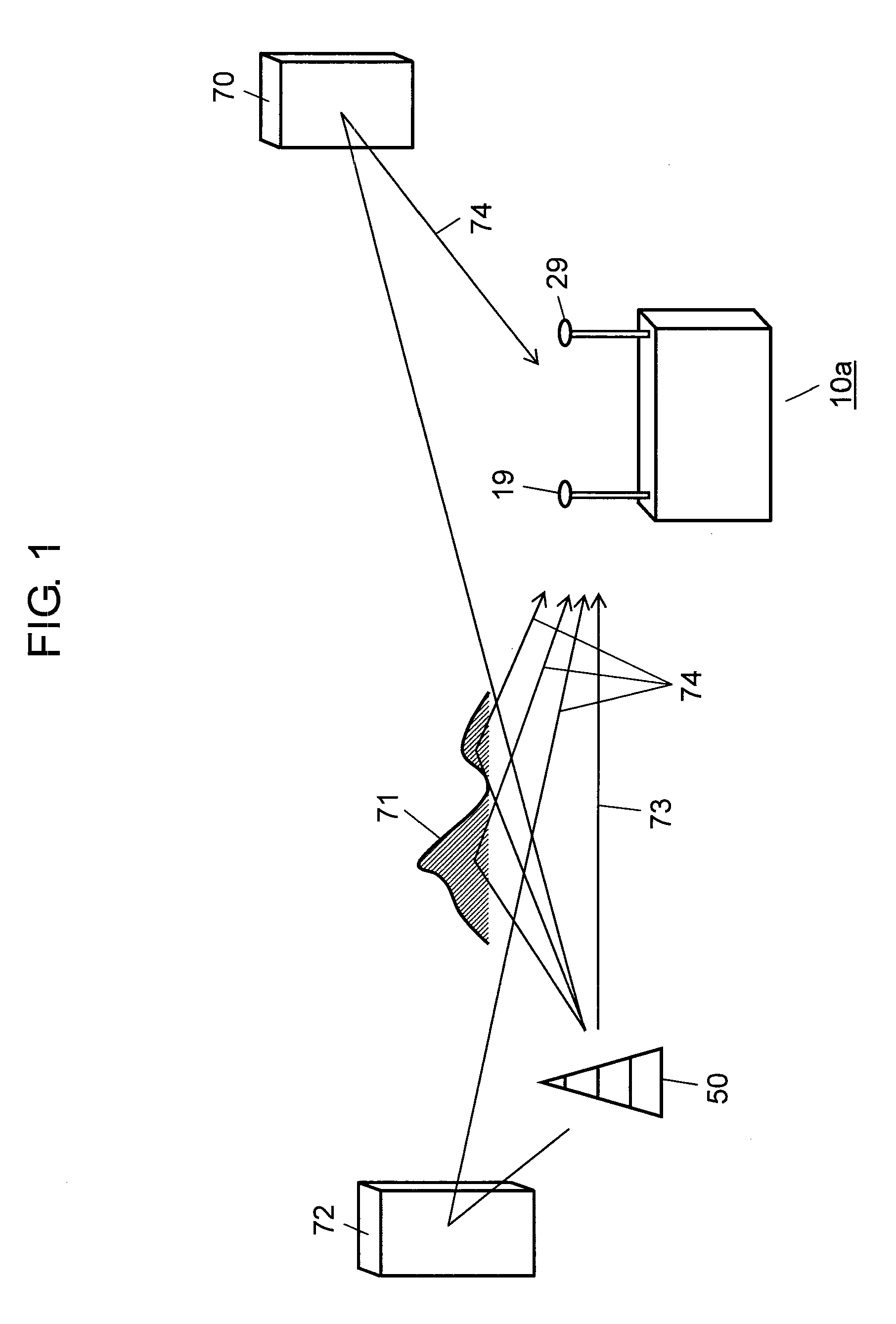
[0065]FIG. 1 is a schematic diagram showing how radio waves reach wireless device 10a having the function of removing the coupling and correlation of antennas according to the present exemplary embodiment in a general environment. Wireless device 10a of the present exemplary embodiment includes first antenna 19 and second antenna 29 having the same plane of polarization.

[0066]In the case of a fixed wireless device, a signal is brought into a house or other indoor places from a strong directional antenna, which is generally mounted on a roof. In the case of a portable device such as wireless device 10a of the present exemplary embodiment, on the other hand, the antenna is omnidirectional and its polarized direction is not uniquely specified because the location and direction of the device keep changing during travel. The reason for using such an antenna is that the plane of polarization changes diversely in order to effectively receive not only direct wave 73 but also indirect wave 7...

second exemplary embodiment

[0100]FIG. 5 is a block diagram of wireless device 10b having the function of removing the coupling and correlation of antennas according to a second exemplary embodiment of the present invention. In the first exemplary embodiment, first and second antennas 19 and 29 are oriented substantially in the same direction as shown in FIG. 2. In wireless device 10b according to the present second exemplary embodiment, on the other hand, first antenna 19 and second antenna 29b are oriented substantially orthogonal to each other as shown by arrow 42 of FIG. 5. More specifically, first antenna 19 receives signals mainly in the vertical plane of polarization, and second antenna 29b receives signals mainly in the horizontal plane of polarization. In the present exemplary embodiment, like components and functions are labeled with like reference numerals with respect to the first exemplary embodiment and hence the description thereof will be omitted.

[0101]Similar to the first exemplary embodiment,...

third exemplary embodiment

[0104]FIG. 6 is a block diagram of wireless device 10c having the function of removing the coupling and correlation of antennas according to a third exemplary embodiment of the present invention. In the first exemplary embodiment, diversity receiver 30 receives the output signal of second antenna 29 directly from matching circuit 21 via second tuner 24 so as to simplify the circuit configuration. In the third exemplary embodiment, on the other hand, as shown in FIG. 6, the system including second antenna 29 has the same structure as the system including first antenna 19 so as to cancel the antenna coupling independently of each other.

[0105]As shown in FIG. 6, wireless device 10c having the function of removing the coupling and correlation of antennas according to the present exemplary embodiment includes, in addition to the structure of the first exemplary embodiment shown in FIG. 2, second sensor 18, second amplitude-phase regulator 22, and second adder 23. The other components and...


PUM


Abstract

A wireless device, which employs the method and function of removing the coupling and correlation of antennas, picks up the noise components released from inside the device together with the current induced to a second antenna. The wireless device then controls the amplitude and phase of the pickup signal so as to optimize the reception quality signal for received signal, and additively combines it with the signal received from the first antenna. The coupled component, which is induced from the first antenna to the second antenna, is cancelled together with the noise component, thus mainly cancelling the largest cause of desensitization. This results in the maximization of the receiving sensitivity.

Description

TECHNICAL FIELD[0001]The present invention relates to a broadcast receiving device, and more particularly, to a receiving device small enough to be portable. The present invention further more particularly relates to a method for removing the coupling and correlation of antennas so as to receive broadcast waves with high sensitivity and stability using the diversity function, and also to a wireless device having the function of removing the coupling and correlation of antennas.BACKGROUND ART[0002]Conventionally, diversity receiving devices are available to receive broadcast waves stably when broadcast receiving devices are on the move. As a method for reducing desensitization due to self noise in a receiver, a noise cancelling technique is disclosed in Patent Literature 1. According to this technique, the noise is first processed to have an opposite phase and an appropriate amplitude, and then injected into the reception circuit so as to cancel the noise.[0003]FIGS. 10 to 12 show a ...

Claims


Application Information

Patent Timeline
Patent Type & Authority Applications(United States)
IPC IPC(8): H04B1/06
CPCH01Q1/521H04B7/08H04B1/126H01Q1/523
Inventor EJIMA, NAOKI
Owner PANASONIC INTELLECTUAL PROPERTY CORP OF AMERICA
Learn More