
Radio apparatus and adaptive array processing method

A wireless device and array processing technology, applied in radio transmission systems, polarization/direction diversity, diversity/multi-antenna systems, etc., can solve problems such as gain drop and interference that cannot be removed

Inactive Publication Date: 2007-09-05
HOKKAIDO UNIVERSITY +1
View PDF2 Cites 0 Cited by
  • Summary
  • Abstract
  • Description
  • Claims
  • Application Information

AI Technical Summary

Problems solved by technology

[0113] Thus, where the antenna degrees of freedom are exhausted, there is a problem that the gain to the direction of the desired wave decreases, or that all interference cannot be removed due to interference that seems to exceed the antenna degrees of freedom

Method used


Image

  • Radio apparatus and adaptive array processing method
  • Radio apparatus and adaptive array processing method
  • Radio apparatus and adaptive array processing method

Examples


Embodiment 1

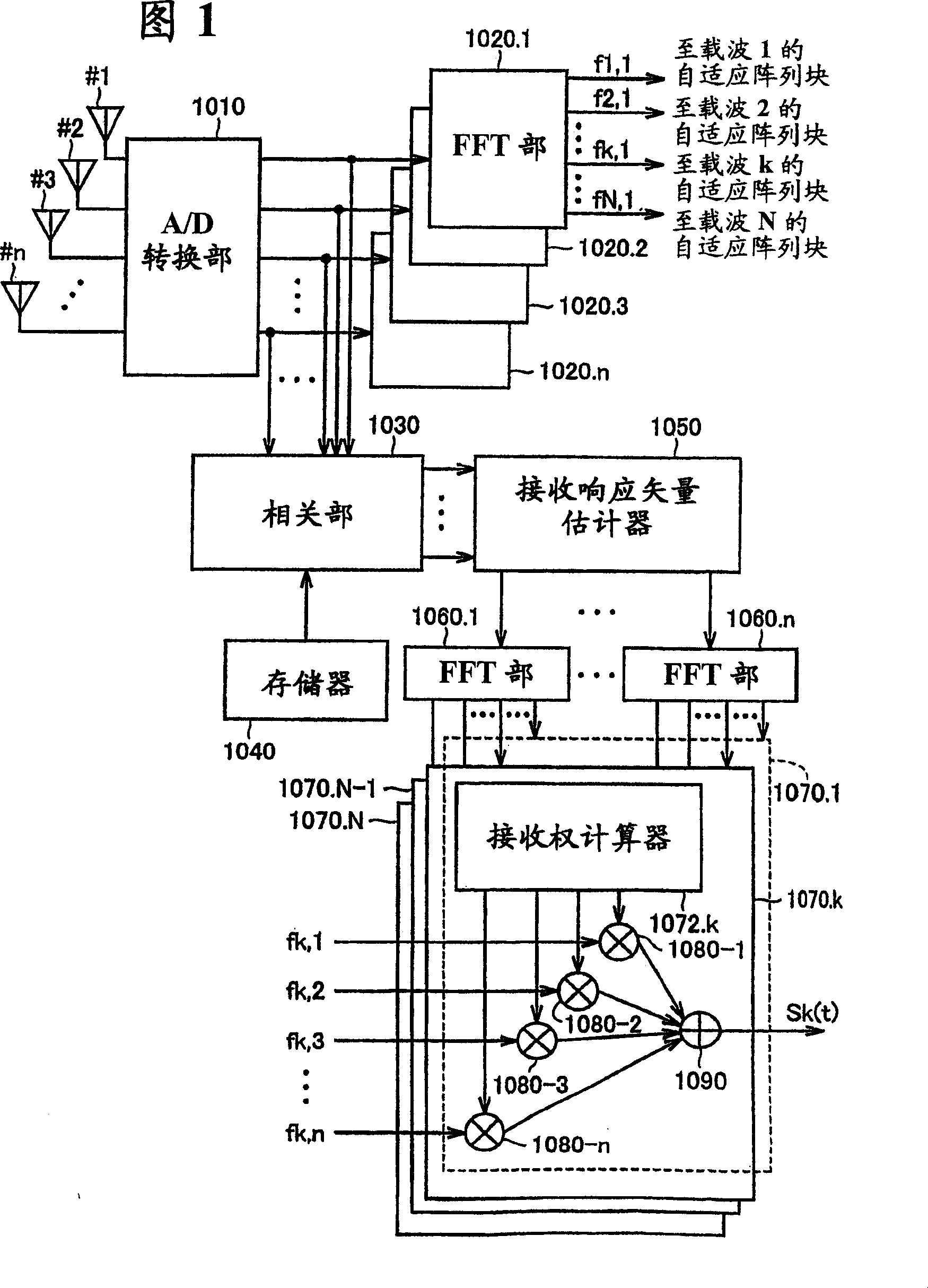
[0153] FIG. 1 is a schematic block diagram showing the configuration of an adaptive array base station 1000 according to an embodiment of the present invention. The adaptive array base station 1000 of the present invention transmits and receives signals having directionality through adaptive array processing between mobile stations such as user terminals. However, as will be understood from the following description, the adaptive array base station 1000 may also transmit and receive signals with mobile stations by using space division multiplexing.

[0154] Referring to Fig. 1, the adaptive array base station 1000 is provided with: an array antenna composed of n (n: natural number) antennas; receiving signals from array antennas #1 to #n, performing detection or A / D conversion of analog / digital conversion Part 1010; set for each antenna, and receive the output from the A / D conversion part 1010 to separate and extract n FFT parts 1020.1~1020.n of the signals of the respective c...

Embodiment 2

[0284] In Embodiment 1, as the operation of reception response vector estimator 1050, the complex response of the desired signal and the complex response of the interference signal are obtained by the method described in equations (22) to (26).

[0285] However, when there is no overlap between the reference signal interval of the desired signal and the reference signal interval of the interference signal, the methods described in equations (22) to (26) cannot be directly used as they are.

[0286] In Embodiment 2, a method of deriving the complex response of the desired signal and the complex response of the interference signal that can be used even in such a case will be described.

[0287] (estimate of expected signal response)

[0288] When finding the complex response of the desired signal, the evaluation function J provided by the following equation (35) is used 2. In addition, unless otherwise specified, the code|symbol in the following formula is the same as formula ...


PUM


Abstract

A correlator detects arriving timings of a desired wave and an interfering wave from a signal transmitted by the OFDM scheme. A reception response vector estimator estimates a first response vector for a signal arriving within a guard interval section from the head arriving wave and a second response vector for a signal arriving after the guard interval section from the head arriving wave out of the desired wave, and also a third response vector for a signal arriving within the guard interval section from the head arriving wave and a fourth response vector for a signal arriving after the guard interval section from the head arriving wave out of the interfering wave. An adaptive array block provides a weight vector based on a result of Fourier transform on the first to fourth response vectors.

Description

technical field [0001] The present invention relates to a structure of a wireless device used in a base station and an adaptive array processing method mainly for wireless communication with a mobile body such as a mobile phone. Background technique [0002] In recent years, in the rapid development of mobile communication systems (for example, Personal Handyphone System: hereinafter referred to as PHS), in order to suppress the influence of interference waves and obtain good communication quality, by receiving An adaptive array base station in which a signal of a desired wave is separated and extracted by performing well-known adaptive array processing on a signal is put into practical use. [0003] In addition, if such an adaptive array base station is used, in order to improve the frequency utilization rate of radio waves, the same time slot of the same frequency can be spatially divided to realize the multiplexing connection of mobile terminal devices of multiple users. ...

Claims


Application Information

Patent Timeline
Patent Type & Authority Patents(China)
IPC IPC(8): H04B7/10H04J11/00H04B7/00H04B7/08H04B7/26H04L1/06H04L25/02H04L27/26
CPCH04B7/0848H04B7/0615H04B7/0857H04B7/0854H04L27/2647H04L25/0228H04L25/022H04L25/0204H04B7/0897H04L27/26
Inventor 小川恭孝大钟武雄土居义晴
Owner HOKKAIDO UNIVERSITY
Learn More