
Non-electronic radio frequency front-end with immunity to electromagnetic pulse damage

a radio frequency front-end and non-electronic technology, applied in the direction of optics, instruments, optical elements, etc., can solve problems such as receiver failur

Inactive Publication Date: 2008-11-11
RGT UNIV OF CALIFORNIA
View PDF5 Cites 10 Cited by
  • Summary
  • Abstract
  • Description
  • Claims
  • Application Information

AI Technical Summary

Benefits of technology

[0014]One aspect of the invention is to eliminate metal electrodes, interconnects and the metal antenna found in conventional equipment. Another aspect of the invention is the use of a dielectric resonance antenna that behaves as a “concentrator” for the received RF power. For example, in one embodiment, an EO modulator is integrated with a dielectric resonance antenna to exploit unique isolation features of photonics. According to another aspect of the invention, doubly (RF and optical) resonant device design maximizes the receiver sensitivity.
[0015]Another aspect of the invention is the integration of high-Q optical EO resonators and dielectric resonant antennas to create an efficient mixing of light and microwave fields. The resulting Non-Electronic RF (NERF) technology brings about a Non-Electronic all-dielectric (NEAD) RF front-end, which provides complete isolation between the air interface and the ensuing electronic circuitry, thereby creating a wireless receiver front end that is immune to directed energy attacks.
[0018]Another aspect of the invention is use of a dielectric resonance antenna to reduce the radar cross section and hence to improve stealth performance of an RF receiver.
[0019]Another aspect of the invention is use a high permittivity material for reducing the antenna aperture size for applications related to EMP and HPM immune receivers.
[0021]Another aspect of the invention is the use of reverse poling of the EO resonator to break its symmetry and to maximize the RF to optical conversion efficiency.

Problems solved by technology

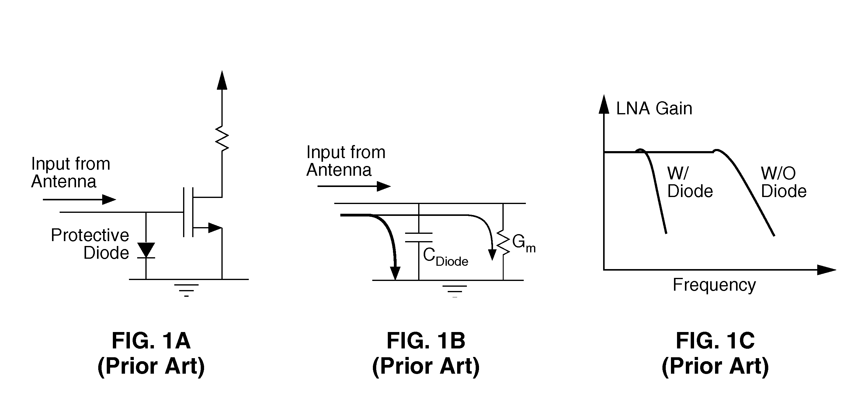
However, because the receiver circuitry is nevertheless damaged, the receiver can fail at a later and unpredictable time that can be during a critical mission.

Method used


Image

  • Non-electronic radio frequency front-end with immunity to electromagnetic pulse damage
  • Non-electronic radio frequency front-end with immunity to electromagnetic pulse damage
  • Non-electronic radio frequency front-end with immunity to electromagnetic pulse damage

Examples


Embodiment Construction

[0044]1. Front End Architecture: Electro-Optic Isolation

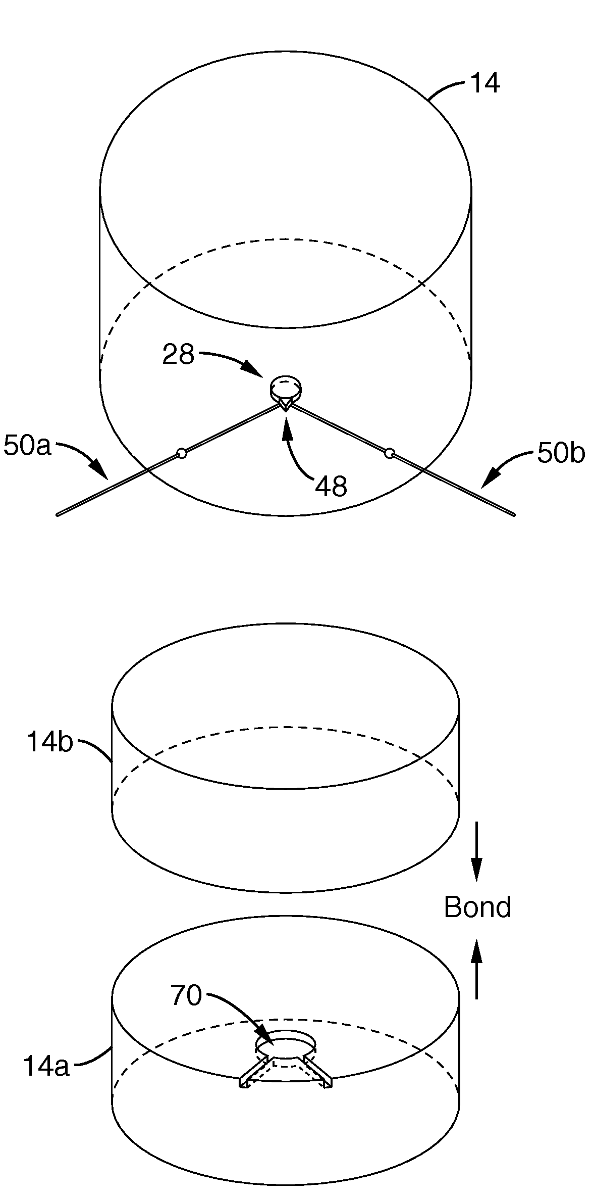
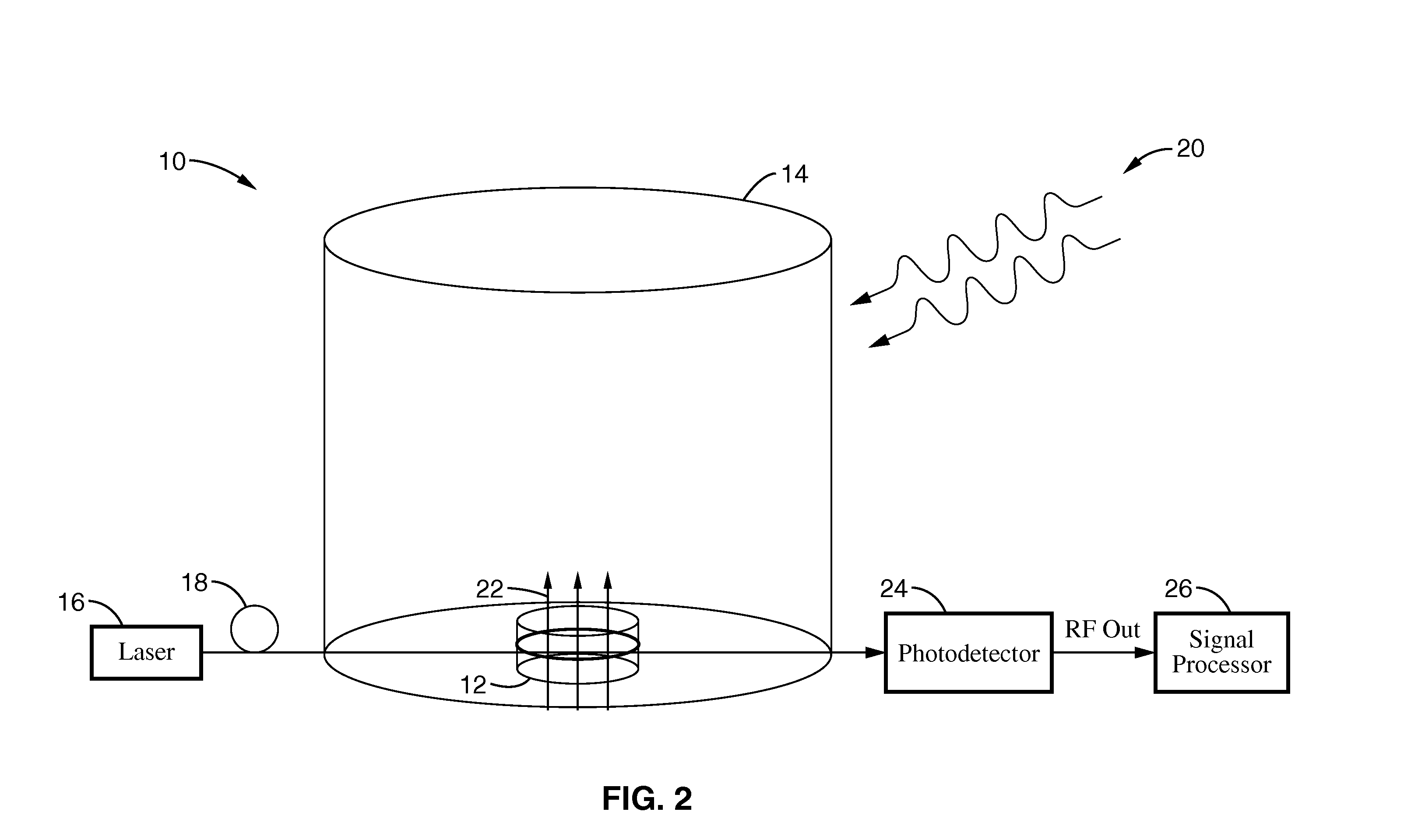
[0045]Referring first to FIG. 2, the architecture of the Non-Electronic RF Front End (NERF) technology of the present invention is illustrated. It will be appreciated from the discussion that follows that the technology can be employed in a radio frequency receiver, a field probe, or a remote RF sensor, and other applications where isolation between the input signal and downstream electronics is required or desirable.

[0046]By way of example, and not of limitation, the invention employs a probe head 10 that provides isolation between the air interface and downstream electronic circuitry. In the embodiments illustrated herein, probe head 10 comprises an electro-optic (EO) resonator 12 integrated with a dielectric resonance antenna (DRA) 14. Light from a laser 16 is launched into an optical fiber 18 that serves as an optical signal carrier. The preferred laser source is a narrow linewidth linearly polarized monochromatic laser whi...


PUM


Abstract

A non-electronic all-dielectric (NEAD) or non-electronic RF (NERF) front-end that exploits isolation features of photonics to eliminate metal electrodes, interconnects and the antenna. An electro-optic (EO) modulator is integrated with a dielectric resonance antenna to exploit unique isolation features of photonics. A doubly (RF and optical) resonant device design maximizes the receiver sensitivity. High-Q optical disk resonators and dielectric resonant antennas are integrated to create an efficient mixing of light and RF fields. The resulting non-electronic RF technology produces an all-dielectric RF front-end which provides complete isolation between the air interface and the ensuing electronic circuitry, enabling the creation of an RF receiver that is immune to high-power electro-magnetic pulses (EMP) and High Power Microwave (HPM) pulses. The device can also be configured as a non-intrusive field probe that co-exists with a conventional receiver and detects a EMP or HPM attack.

Description

CROSS-REFERENCE TO RELATED APPLICATIONS[0001]This application claims priority from U.S. patent application Ser. No. 60 / 721,269 filed on Sep. 27, 2005, incorporated herein by reference in its entirety.STATEMENT REGARDING FEDERALLY SPONSORED RESEARCH OR DEVELOPMENT[0002]This invention was made with Government support under Grant No. FA8750-05-1-0101 (AFRL) awarded by the Defense Advanced Research Projects Agency (DARPA). The Government has certain rights in this invention.INCORPORATION-BY-REFERENCE OF MATERIAL SUBMITTED ON A COMPACT DISC[0003]Not ApplicableBACKGROUND OF THE INVENTION[0004]1. Field of Invention[0005]This invention pertains generally to protecting electronic equipment from electromagnetic pulses, and more particularly to a radio frequency (RF) front end designed for immunity to electromagnetic pulses.[0006]2. Description of Related Art[0007]The Graham Commission report, made to U.S. Congress' House Armed Services Committee on Jul. 22, 2004, concluded that a “high-altitu...

Claims


Application Information

Patent Timeline
Patent Type & Authority Patents(United States)
IPC IPC(8): G02B6/00
CPCG01R29/0885H01Q9/0485
Inventor JALALI, BAHRAMHSU, CHIA-JENHOUSHMAND, BIJAN
Owner RGT UNIV OF CALIFORNIA
Learn More