

Radar frequency hopping
a frequency hopping and radar technology, applied in the field of radar systems, can solve the problems of reducing the sensitivity and maximum detection range, and the overlap of co-locating radars of the same type, so as to avoid extended reception of interfering signals and maximize receiver sensitivity
- Summary
- Abstract
- Description
- Claims
- Application Information
AI Technical Summary
Benefits of technology
Problems solved by technology
Method used
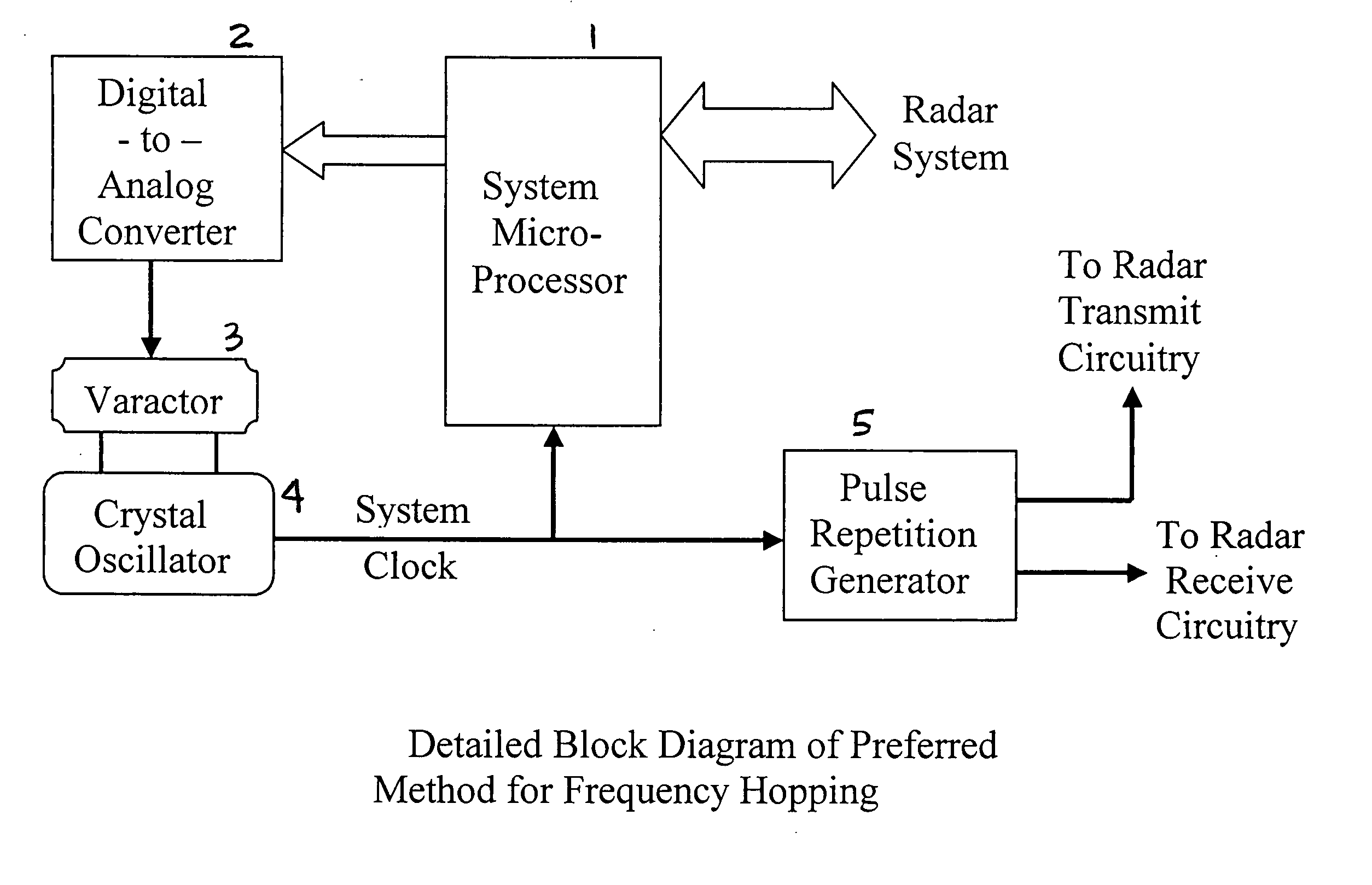
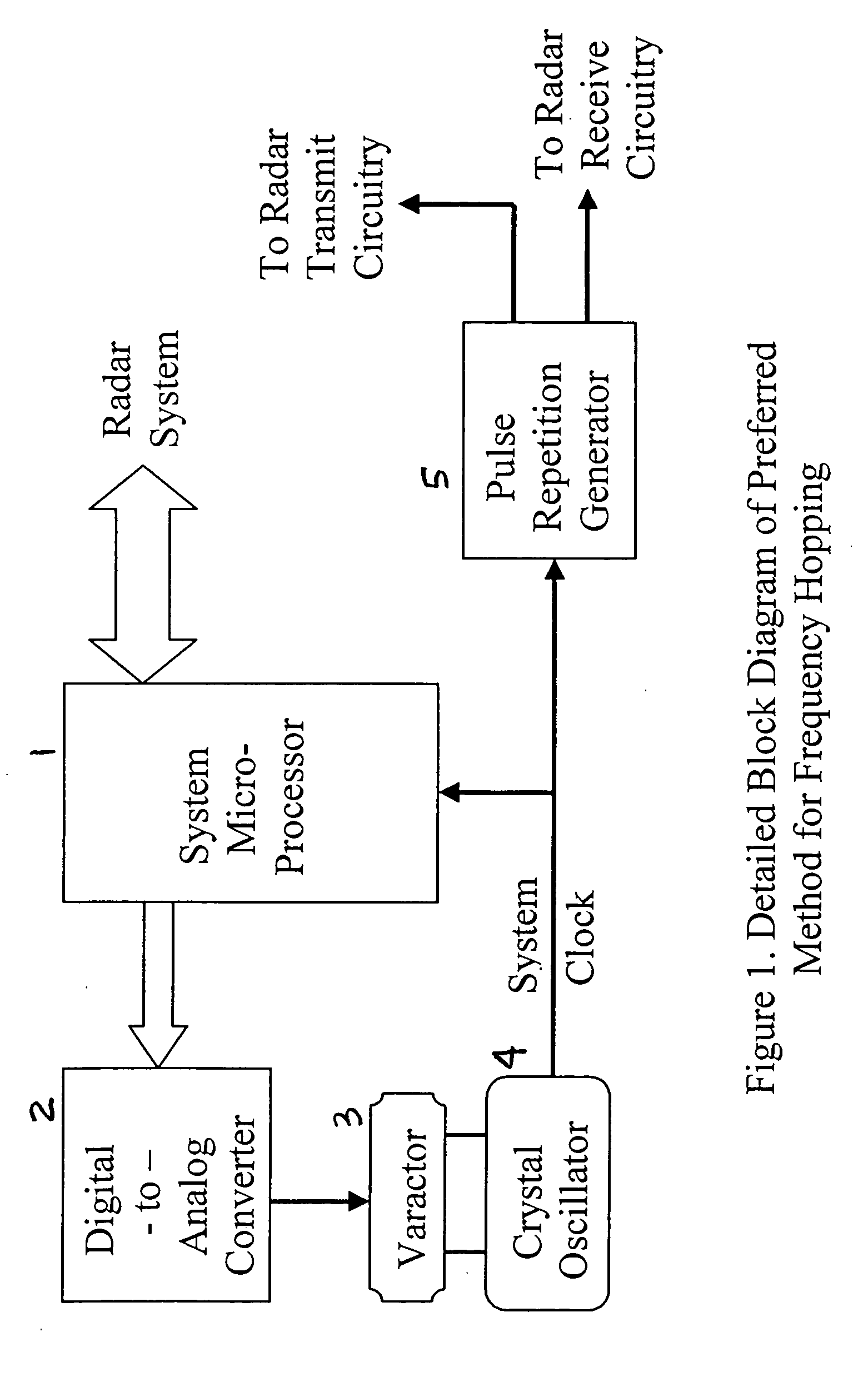
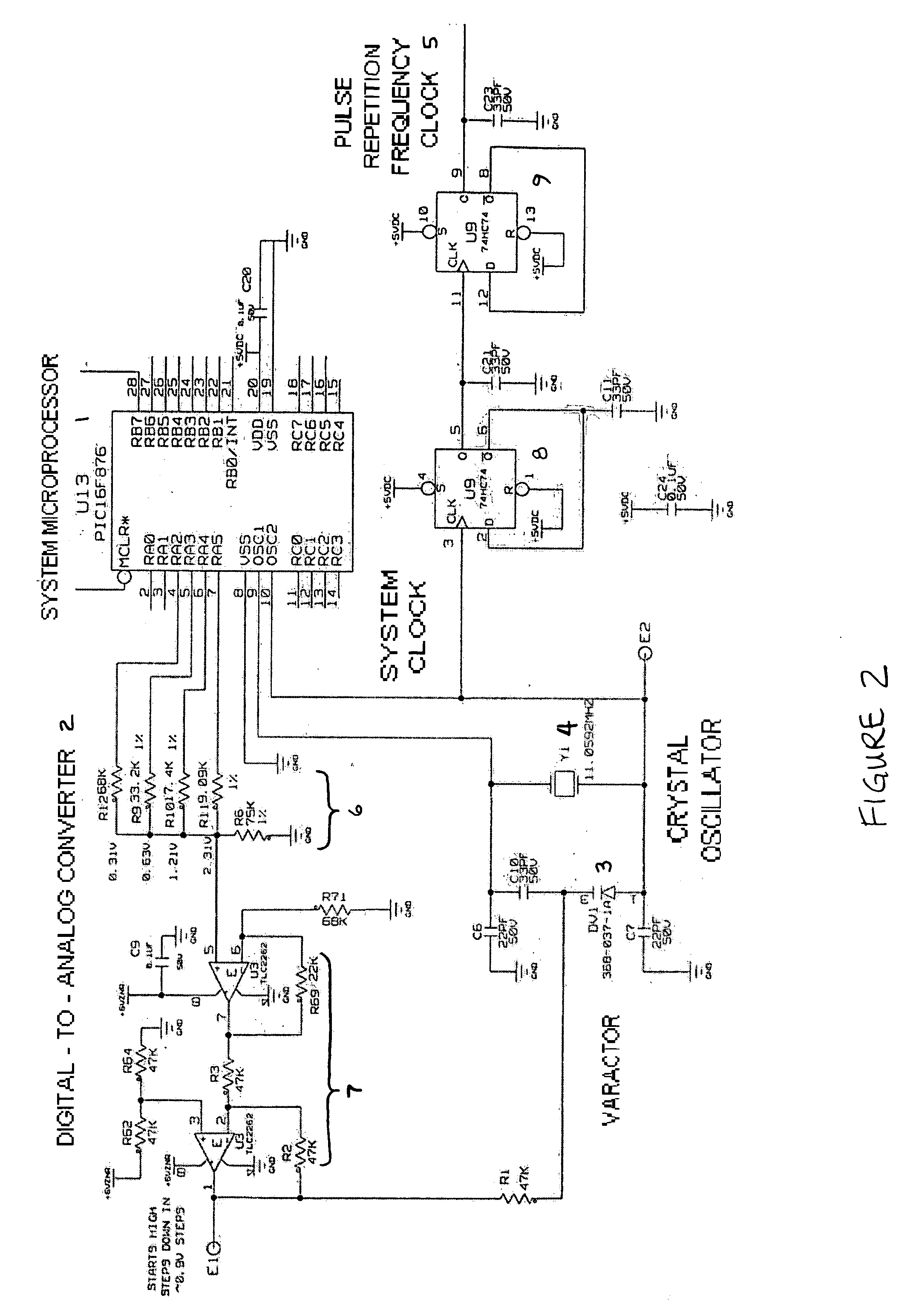
Image

Examples
Embodiment Construction
[0029] As regards the present invention, it should be noted that the circuitry and methods that are described herein and that are claimed are intended to control any variety of radar systems. Classes of radar include but are not limited to the Time Domain Downconversion Radar (TDDC), described above, as well as conventional radars.
[0030] In conventional radar technology, an RF carrier is generated either directly by an RF oscillator or via some up-conversion technique. Up-conversion methods would most commonly consist of an information signal being generated at a frequency considerably lower than the intended RF carrier. This signal would then be fed into a mixer fed by an RF oscillator such that one of the frequency-domain summation terms from the mixer would be used as the intended transmit signal. The basics of this technique would be similar for CW Doppler radars (including FM CW) and pulsed radars, which come in a great variety of versions and modulation types (chirp, pulsed, ...
PUM
 Abstract
Description
Claims
Application Information