
Radar frequency hopping

a frequency hopping and radar technology, applied in the field of radar systems, can solve the problems of reducing the sensitivity and maximum detection range, and the overlap of co-locating radars of the same type, so as to avoid extended reception of interfering signals and maximize receiver sensitivity

Active Publication Date: 2007-05-08
PRECO ELECTRONICS
View PDF17 Cites 9 Cited by
  • Summary
  • Abstract
  • Description
  • Claims
  • Application Information

AI Technical Summary

Benefits of technology

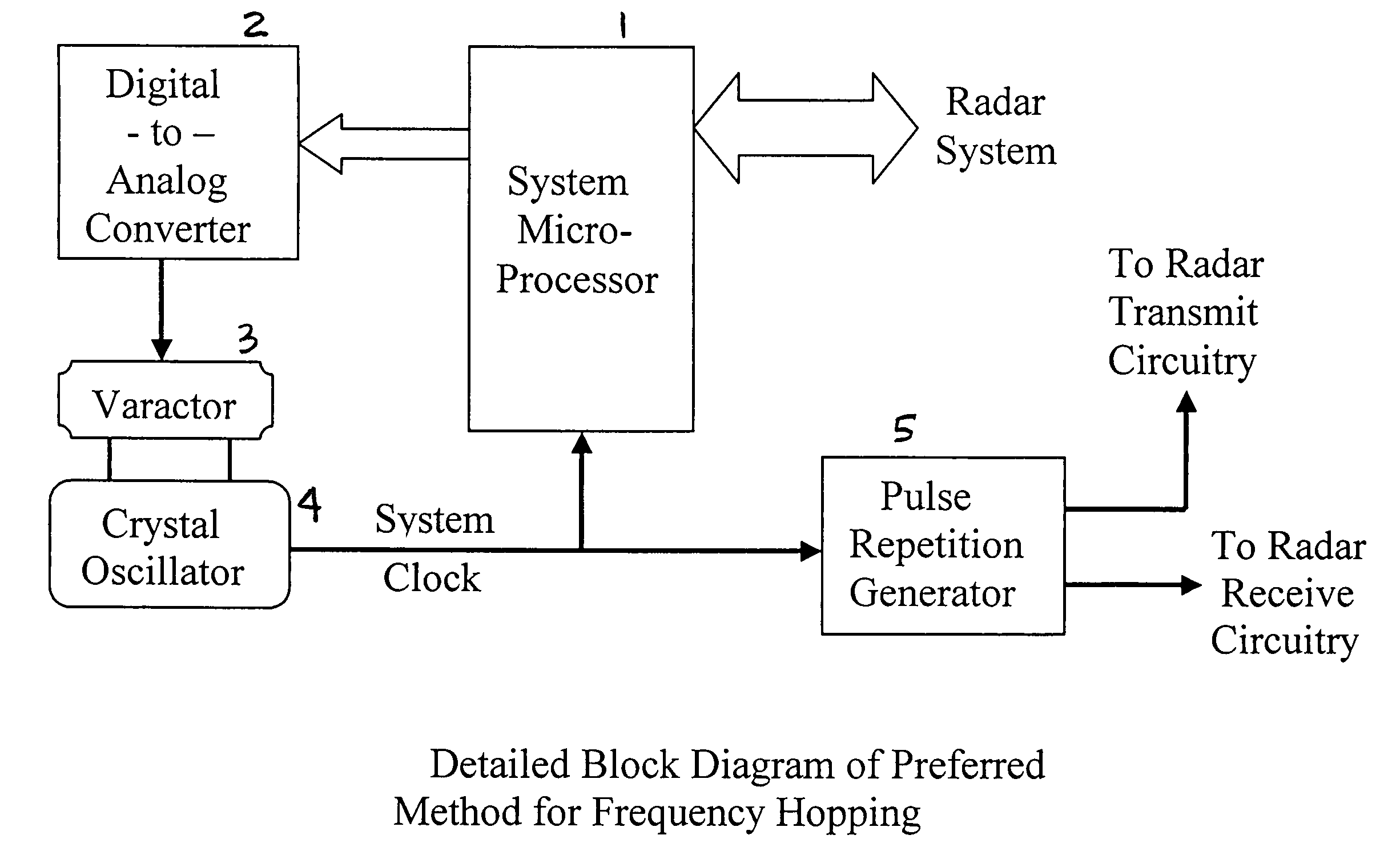
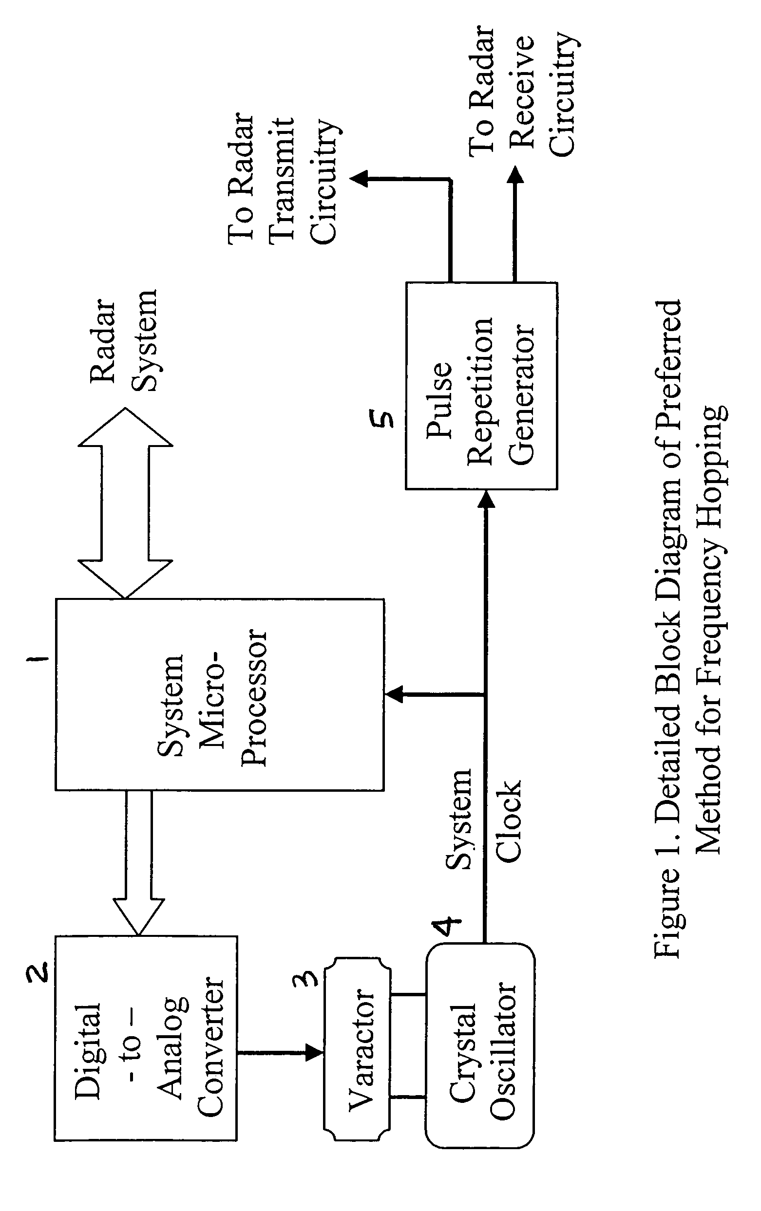
[0015]The present invention comprises apparatus and methods for adjusting or “hopping” the center frequency or the pulse repetition frequency of a radar. Preferably, the invented apparatus and methods provide control of a radar wherein the system timing reference frequency is repeatedly adjusted, from one stable system timing reference frequency to another. This may have the advantages of a) maximizing receiver sensitivity, b) not utilizing any single system timing reference frequency for an extended period of time, and c) avoiding extended reception of interfering signals in a region, including other similar transceivers.
[0017]Presently, the inventor prefers to utilize the fundamental techniques developed for Ultra-Wideband Radar UWB, in conjunction with band-limited transmissions. The invented technology may be implemented using radio frequency electronics that are far simpler than conventional radars. This allows for a significant cost reduction, and also a high-level of inherent noise immunity. As known in the industry, the TDDC radar method is accomplished using a repeated micro-sampling of an RF signal. Echoes from the originally transmitted RF signal are gradually reconstructed using at a much lower frequency, in the process known as downconversion, by sweeping the sampler in time and integrating, or summing, all of the samples, which typically number in the thousands to millions per sweep.
[0022]The traditional approach for improving upon the interference rejection, especially for co-located TDDC devices, is to “dither” the pulse clocks. The technique of randomly dithering is accomplished when the synchronized transmit and receive clocks simultaneously move in frequency a small amount for each individual pulse or so. Dithering the Pulse Repetition Frequency (PRF) for each pulse is used successfully since the relative transmit time and sampling time still remain coherent with respect to one another. The price paid for this technique is an increased noise floor in the receiver. This is likely due to the equivalence of oscillator phase-noise although there may be other noise sources introduced by the constant shifting of the system clock. This naturally limits the maximum range that a radar can operate and the minimum target it can detect.
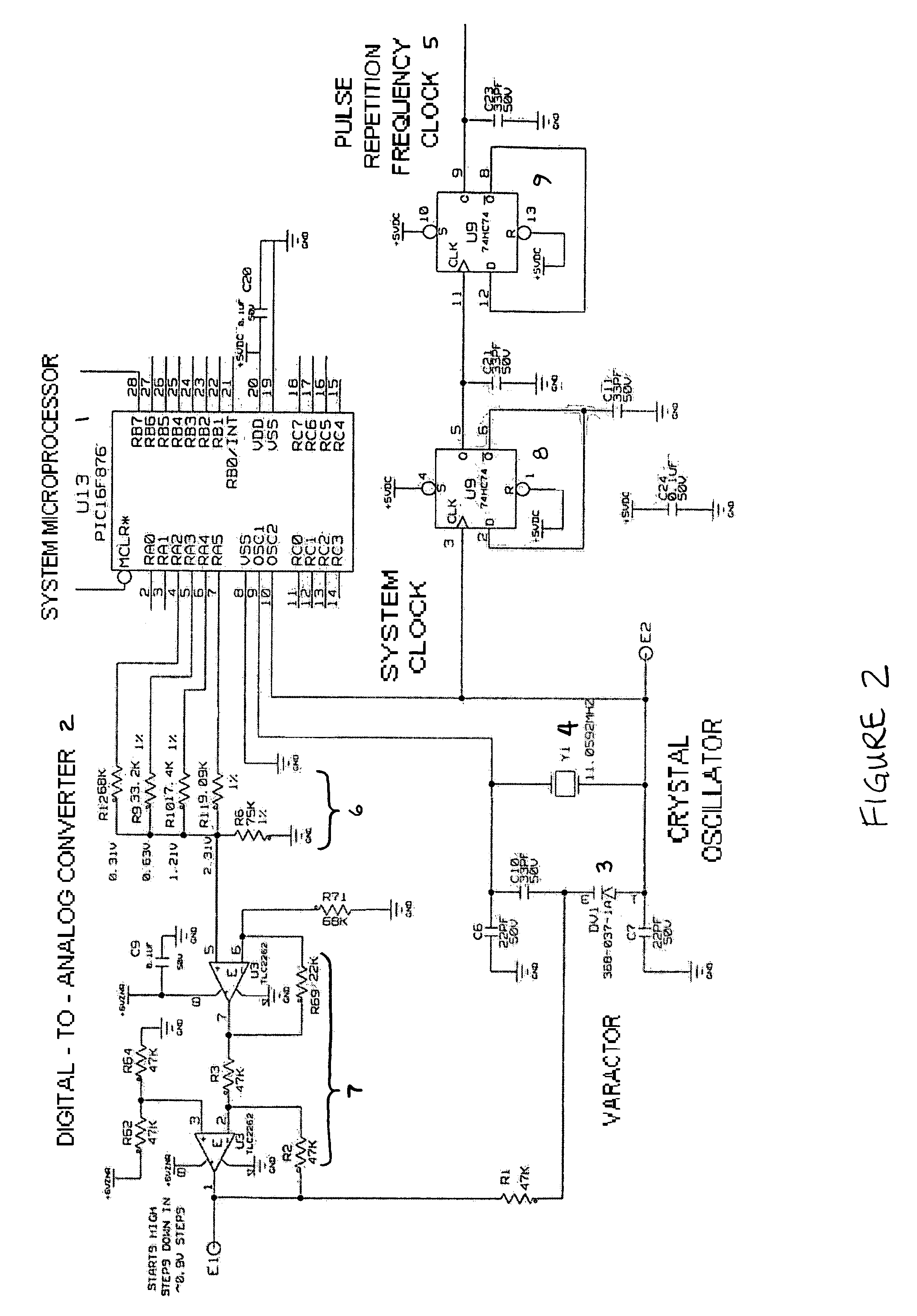
[0024]The present invention preferably “hops” the oscillators to a new frequency at some controlled time, with the “hop” being a set, discreet amount. In the case of a radar, an ideal time to change the clock is during reset of the range sweep. This technique keeps the timing clock stable for a long period of time (long relative to the individual pulses), thus minimizing the noise floor and increasing sensitivity. Then, the oscillator changes to a new stable frequency. If there happens to be interference at some frequency, the interference will most likely last only for the dwell time that the clock stays at that particular frequency. Once the oscillator hops to a new frequency, the interference should cease. Fortunately, the inherent interference rejection of the TDDC technique makes any interference a very narrowband phenomenon, and the frequency hops can be quite small and still be successful. In most typical systems, the clock dwell time will likely be a few tens of milliseconds or so per range sweep, thus minimizing the effects of interference occurring for a sustained period of time.

Problems solved by technology

This technique can work well, but it has the effect of raising the system noise floor in practice, and results in a reduction of sensitivity and maximum detection range.
Co-locating radars of the same type can easily overlap, since oscillators are similar, and interference occurs if another signal falls within the intended receiver's sampling window.

Method used


Image

  • Radar frequency hopping
  • Radar frequency hopping
  • Radar frequency hopping

Examples


Embodiment Construction

[0029]As regards the present invention, it should be noted that the circuitry and methods that are described herein and that are claimed are intended to control any variety of radar systems. Classes of radar include but are not limited to the Time Domain Downconversion Radar (TDDC), described above, as well as conventional radars.

[0030]In conventional radar technology, an RF carrier is generated either directly by an RF oscillator or via some up-conversion technique. Up-conversion methods would most commonly consist of an information signal being generated at a frequency considerably lower than the intended RF carrier. This signal would then be fed into a mixer fed by an RF oscillator such that one of the frequency-domain summation terms from the mixer would be used as the intended transmit signal. The basics of this technique would be similar for CW Doppler radars (including FM CW) and pulsed radars, which come in a great variety of versions and modulation types (chirp, pulsed, pul...


PUM


Abstract

Apparatus and methods for adjusting or “hopping” the center frequency or the pulse repetition frequency of a radar system improve the co-locatability of multiple radars commonly located in a region. In a Time Domain Downconversion (TDDC) or Ultra-Wideband (UWB) radar system having a display update period between range sweeps, the preferred device comprises a frequency variable oscillator for adjusting the radar's internal timing reference frequency during a plurality of the display update periods. Radar frequency hopping methods and apparatus may result in improvements in interference immunity compared to other interference reduction techniques and may achieve cost reduction. In frequency hopping radar, if an actual target is present, the receiver waveform will repeat at the newly adjusted center frequency. Confirmation of a target is realized as an ongoing reflection and not interference.

Description

FIELD OF THE INVENTION[0001]The present invention relates generally to radar systems, and, more specifically, to techniques that improve co-locatability and provide reduction of signal interference in radar systems.RELATED ART[0002]In the radar industry, it is known that a class of radar has been developed and widely patented by Thomas McEwan of Lawrence Livermore National Laboratory (LLNL) over the past 8–9 years. This type of radar is referred to as Time Domain Downconversion or TDDC technology, and is also commonly referred to as “carrier free”, “baseband pulse”, “impulse”, “ultra-wideband” or UWB, and / or “integrated sampling down-conversion” radar. While conventional mixer-based radar technology is based upon frequency domain physics, the integrated sampling technique of TDDC directly converts the actual RF time-domain waveform into an expanded time-scale replica of the original waveform (hence, Time Domain Downconversion).[0003]TDDC represents technology that enables micro impu...

Claims


Application Information

Patent Timeline
Patent Type & Authority Patents(United States)
IPC IPC(8): G01S7/28G01S7/40G01S13/02G01S13/87
CPCG01S7/4004G01S13/0209G01S13/87
Inventor BANDHAUER, BRIAN
Owner PRECO ELECTRONICS
Learn More