Wireless communication apparatus

a technology of wireless communication and wireless communication equipment, which is applied in the field of wireless communication equipment, can solve the problems of not knowing how to bring the resonance frequency of the antenna back into agreement with the reference frequency of the predetermined signal, and achieve the effects of reducing the sensitivity of the receiver reducing the parts count and and reducing the size of the second wireless communication apparatus

Inactive Publication Date: 2013-06-11
NIPPON SOKEN +1
View PDF12 Cites 0 Cited by
  • Summary
  • Abstract
  • Description
  • Claims
  • Application Information

AI Technical Summary

Benefits of technology

[0011]Consequently, when the impedance of the first antenna is changed due to a change in arrangement of metal members around the first antenna and the resonance frequency of the first antenna is deviated from the reference frequency due to the change in the impedance, it is possible for the controller to bring the resonance frequency of the first antenna back into agreement with the reference frequency by controlling the impedance of the impedance matching circuit. As a result, the receiver sensitivity of the first wireless communication apparatus to the predetermined signal transmitted by the external transmitter can be maximized despite the change in arrangement of metal members around the first antenna.
[0012]Moreover, since the single oscillator is used for both the frequency conversion by the frequency conversion circuit in the reception mode and the recovery of the resonance frequency of the first antenna to the reference frequency in the tuning mode, it is possible to reduce both the parts count and size of the first wireless communication apparatus.
[0016]Consequently, when the impedance of the antenna is changed due to a change in arrangement of metal members around the antenna and the resonance frequency of the antenna is deviated from the reference frequency due to the change in the impedance, it is possible for the controller to bring the resonance frequency of the antenna back into agreement with the reference frequency by controlling the impedance of the impedance matching circuit. As a result, the receiver sensitivity of the second wireless communication apparatus to the predetermined signal transmitted by the external transmitter can be maximized despite the change in arrangement of metal members around the antenna.
[0017]Moreover, since the single oscillator is used for both the frequency conversion by the frequency conversion circuit in the reception mode and the recovery of the resonance frequency of the antenna to the reference frequency in the tuning mode, it is possible to reduce both the parts count and size of the second wireless communication apparatus.
[0018]Furthermore, in the second wireless communication apparatus, the single antenna is employed as a common antenna for receiving both the predetermined signal transmitted by the external transmitter and the frequency signal output from the oscillator. Consequently, it is possible to further reduce both the parts count and size of the second wireless communication apparatus.

Problems solved by technology

However, from the prior art, it is unknown how to bring the resonance frequency of the antenna back into agreement with the reference frequency of the predetermined signals in such cases.
Therefore, when the reception circuit is implemented by an Integrated Circuit (IC), it is unnecessary to wire between the IC and the impedance matching circuit and thus unnecessary to modify the IC.

Method used


Image

  • Wireless communication apparatus
  • Wireless communication apparatus
  • Wireless communication apparatus

Examples


Embodiment Construction

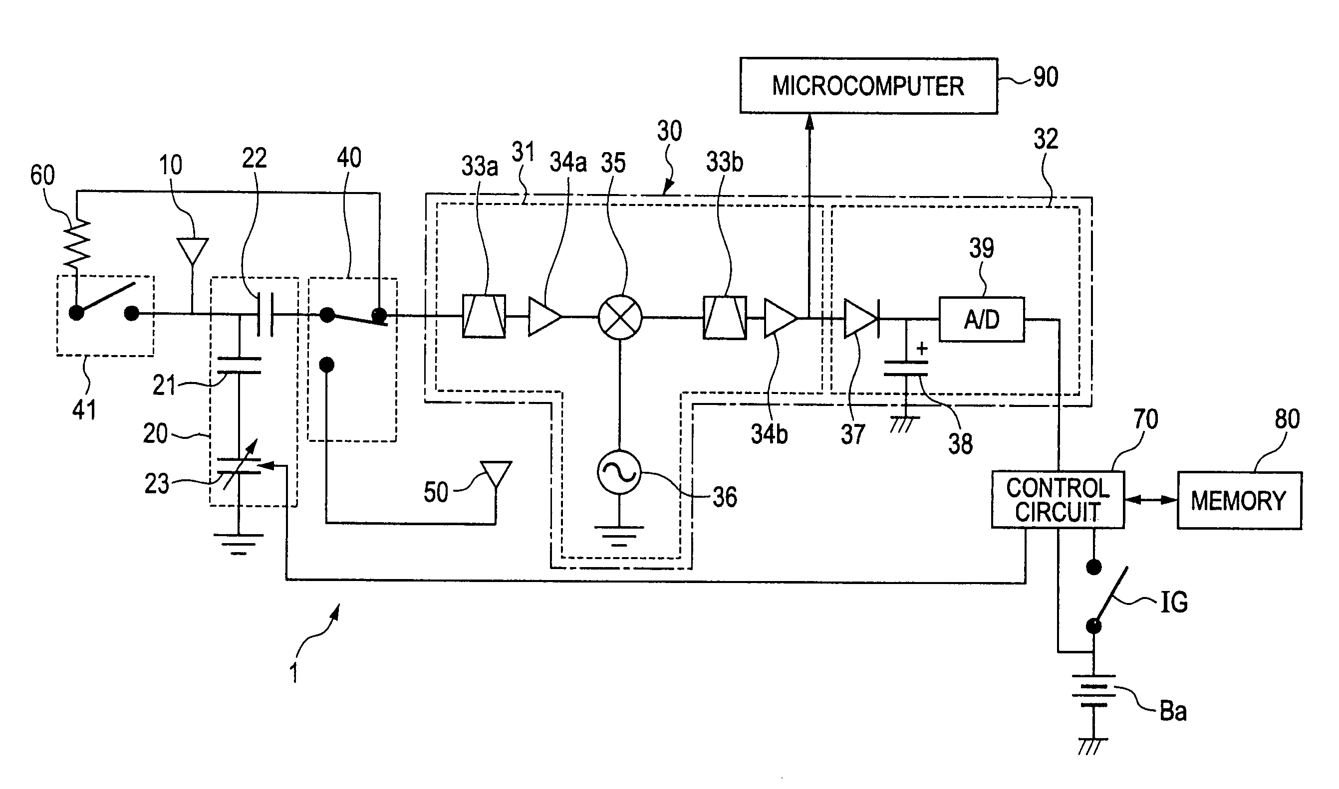
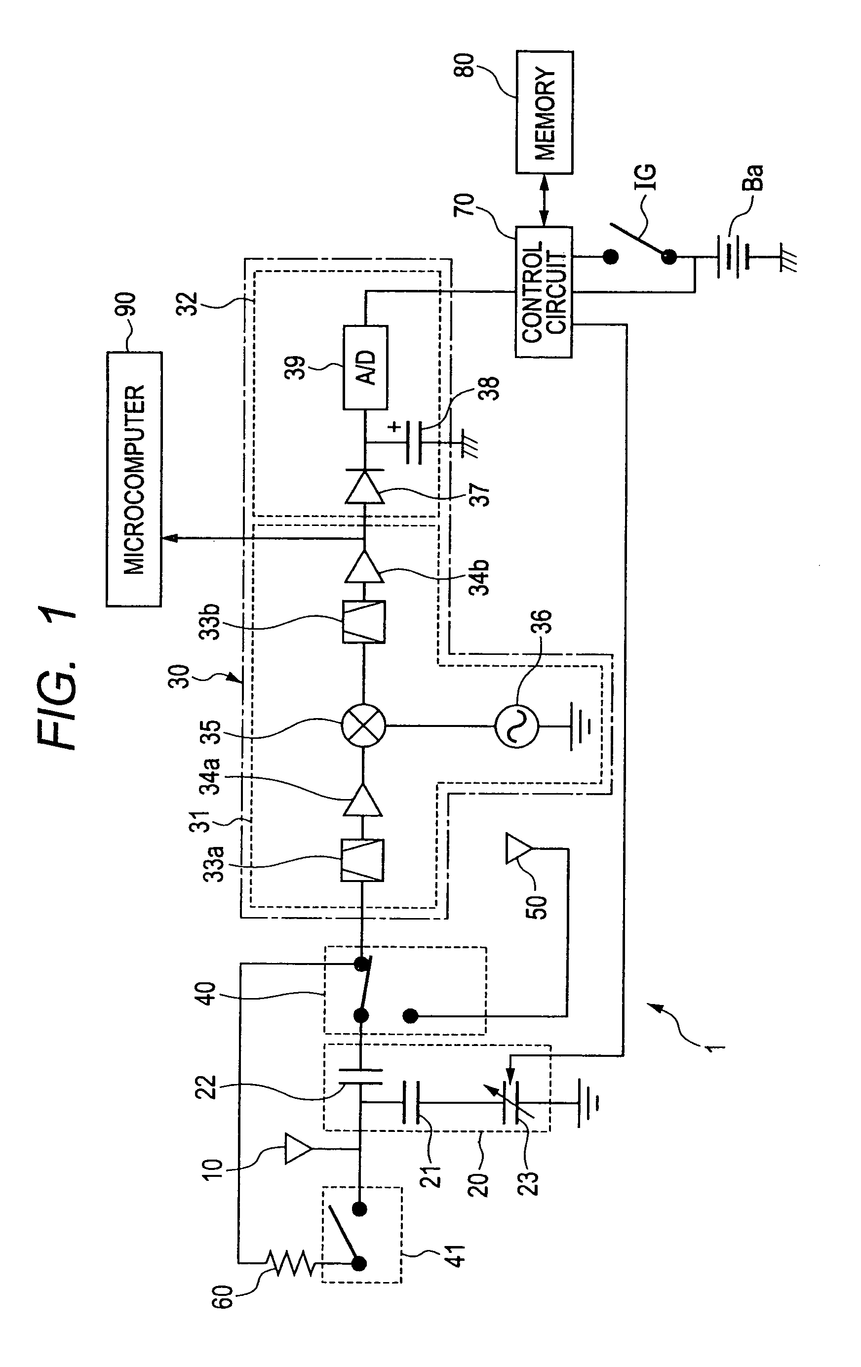
[0034]FIG. 1 shows the overall configuration of a wireless communication apparatus 1 according to a preferred embodiment of the invention.

[0035]The wireless communication apparatus 1 according to the embodiment may be employed, for example, as a receiver in a Smart Entry System to receive predetermined signals transmitted by a portable transmitter (not shown) of the system. The Smart Entry System is a remote keyless entry system for a motor vehicle, which has been developed by Toyota Motor Corporation. Further, the wireless communication apparatus 1 may be arranged, for example, in the vicinity of a C-pillar of the vehicle. In addition, the wireless communication apparatus 1 is designed so as to be capable of being used in different types of motor vehicles.

[0036]As shown in FIG. 1, the wireless communication apparatus 1 includes a first antenna 10, an impedance matching circuit 20, a reception circuit 30, first and second switches 40 and 41, a second antenna 50, a resistor element 6...


PUM


Abstract

In a wireless communication apparatus, when a first switch electrically connects a second antenna to an impedance matching circuit and a second switch electrically connects a first antenna to a reception circuit, a frequency signal output from an oscillator of the reception circuit is received by the second antenna and applied to the impedance matching circuit. Then, a controller controls the impedance of the impedance matching circuit so as to bring a RSSI voltage output from a signal strength detection circuit of the reception circuit into agreement with a reference RSSI voltage, thereby bringing the reference frequency of the first antenna into agreement with a reference frequency.

Description

CROSS-REFERENCE TO RELATED APPLICATION[0001]This application is based on and claims priority from Japanese Patent Application No. 2010-116537, filed on May 20, 2010, the content of which is hereby incorporated by reference in its entirety into this application.BACKGROUND[0002]1. Technical Field[0003]The present invention relates to wireless communication apparatuses that receive signals via antennas.[0004]2. Description of Related Art[0005]A conventional wireless communication apparatus includes an antenna for receiving predetermined signals having a reference frequency, a resonance circuit that includes a capacitor and resonates with the antenna, a capacitance varying circuit that varies the capacitance of the capacitor of the resonance circuit, an oscillation circuit that applies a test signal to the resonance circuit, a voltage detection circuit that detects the output voltage of the resonance circuit, and a control circuit that controls the capacitance of the capacitor of the re...

Claims


Application Information

Patent Timeline
Patent Type & Authority Patents(United States)
IPC IPC(8): H04B1/44
CPCH03H7/40H04B1/18
Inventor KAKUYA, YUUJITAKAOKA, AKIRAMATSUMOTO, MUNENORISEKINE, TOMOTSUGU
Owner NIPPON SOKEN
Why Eureka
Try Eureka