
Passive optical network system and method of data transmission in the passive optical network

a passive optical network and optical network technology, applied in the field of optical network systems, can solve the problems of poor reception sensitivity and inability to meet the level diagram of the existing system, and achieve the effect of improving the reception sensitivity of the second optical network unit and improving the high speed sid

Inactive Publication Date: 2008-09-18
FUJITSU LTD
View PDF4 Cites 11 Cited by
  • Summary
  • Abstract
  • Description
  • Claims
  • Application Information

AI Technical Summary

Benefits of technology

[0013]The present invention addresses the above mentioned points, with an object of providing a technique that can improve the minimum reception level of an ONU that corresponds to a high speed bit rate without having an influence on an ONU that corresponds to a low speed bit rate, in a PON system in which data of different bit rates coexists.
[0019]Accordingly to the present invention as described above, the receiver sensitivity of the second optical network unit on the high speed side can be improved without having an influence on the reception processing of the data in the first optical network unit on the low speed side. Consequently, a predetermined level diagram can be satisfied, and it is possible to realize a passive optical network system in which data of different bit rates coexists.

Problems solved by technology

However, for the ONU that corresponds to the high speed bit rate, since the band width is wide, this is susceptible to influence of noise, and compared to the ONU that corresponds to the low speed bit rate, receiver sensitivity is poor.
Therefore, if an ONU that corresponds to 10 Gbps is added to an existing system that corresponds to a bit rate of 2.5 Gbps or the like, then in the ONU that corresponds to 10 Gbps it becomes difficult to ensure a minimum reception rate of −28 dBm specified by the aforementioned G-PON_Class_B+, and a problem arises in that the level diagram of the existing system cannot be satisfied.

Method used


Image

  • Passive optical network system and method of data transmission in the passive optical network
  • Passive optical network system and method of data transmission in the passive optical network
  • Passive optical network system and method of data transmission in the passive optical network

Examples


Embodiment Construction

[0028]Hereunder is a description of a best mode for carrying out the present invention, with reference to the appended drawings.

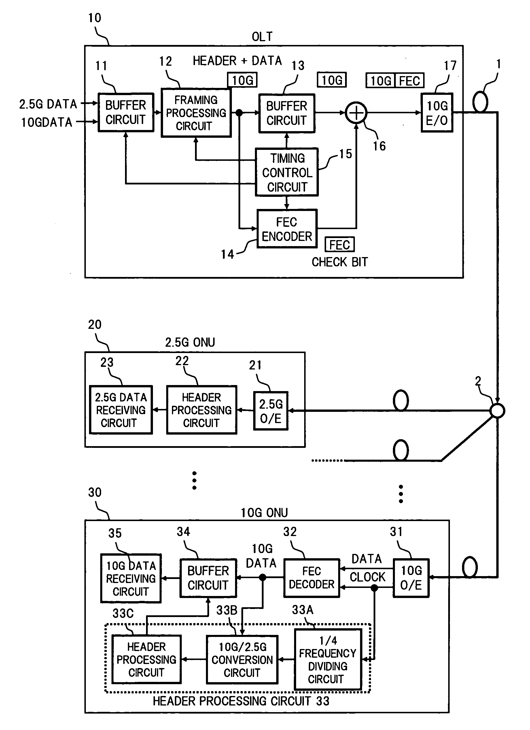
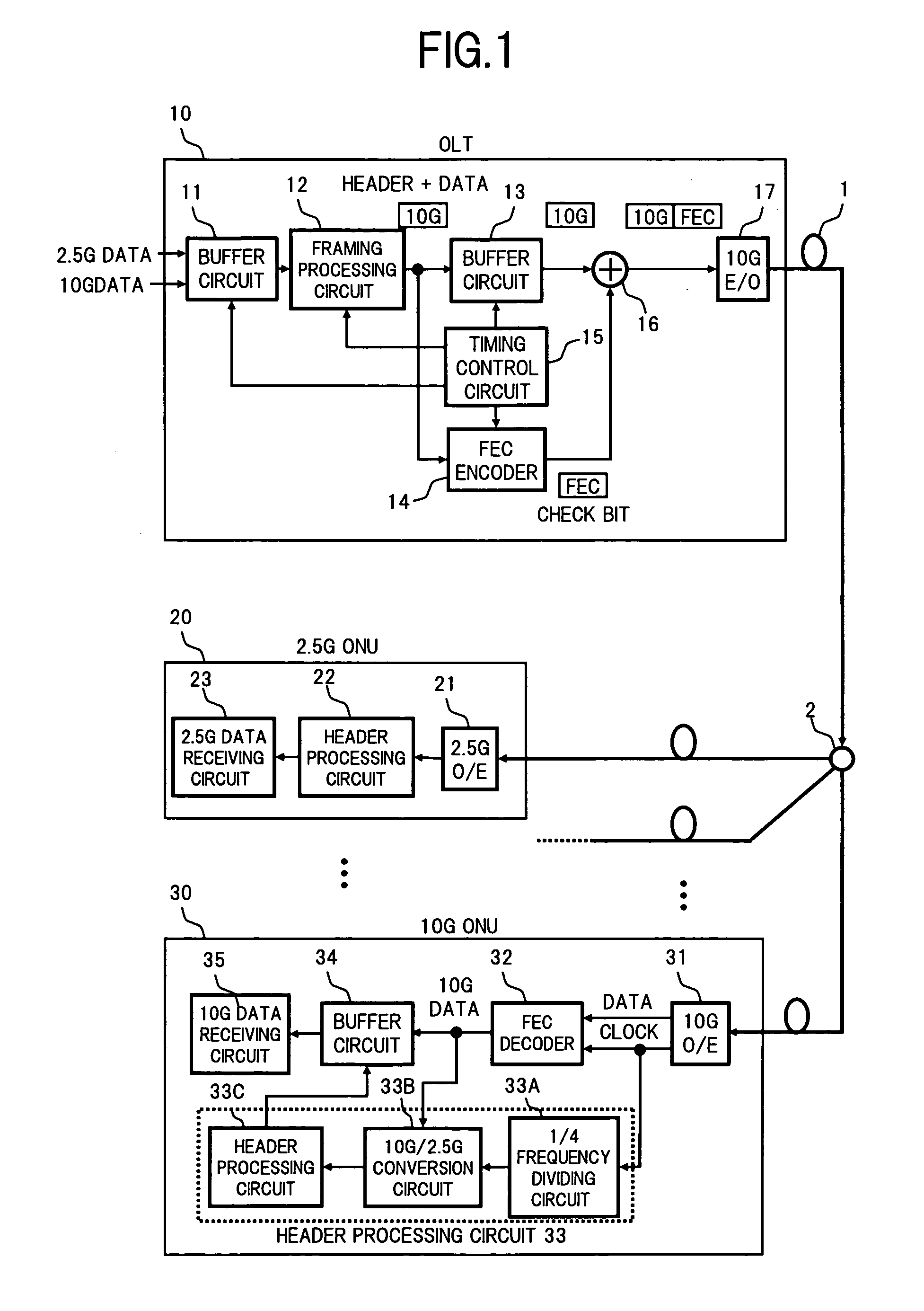
[0029]FIG. 1 is a block diagram showing a configuration of a PON system, according to a first embodiment of the present invention.

[0030]In FIG. 1, the PON system comprises for example: an optical line terminal (OLT) 10 provided on an aggregated station; an optical network unit (ONU) 20 that corresponds to data of 2.5 Gbps and an ONU 30 that corresponds to data of 10 Gbps, arranged respectively corresponding to a plurality of subscribers; an optical transmission line 1 that connects between the OLT 10 and the respective ONUs 20 and 30, and a power splitter 2.

[0031]In FIG. 1 is shown a configuration corresponding to data transmission in the downstream direction from the OLT 10 to the respective ONUs 20 and 30. A configuration corresponding to data transmission in an upstream direction from the respective ONUs 20 and 30 towards the OLT 10 is basically similar ...


PUM


Abstract

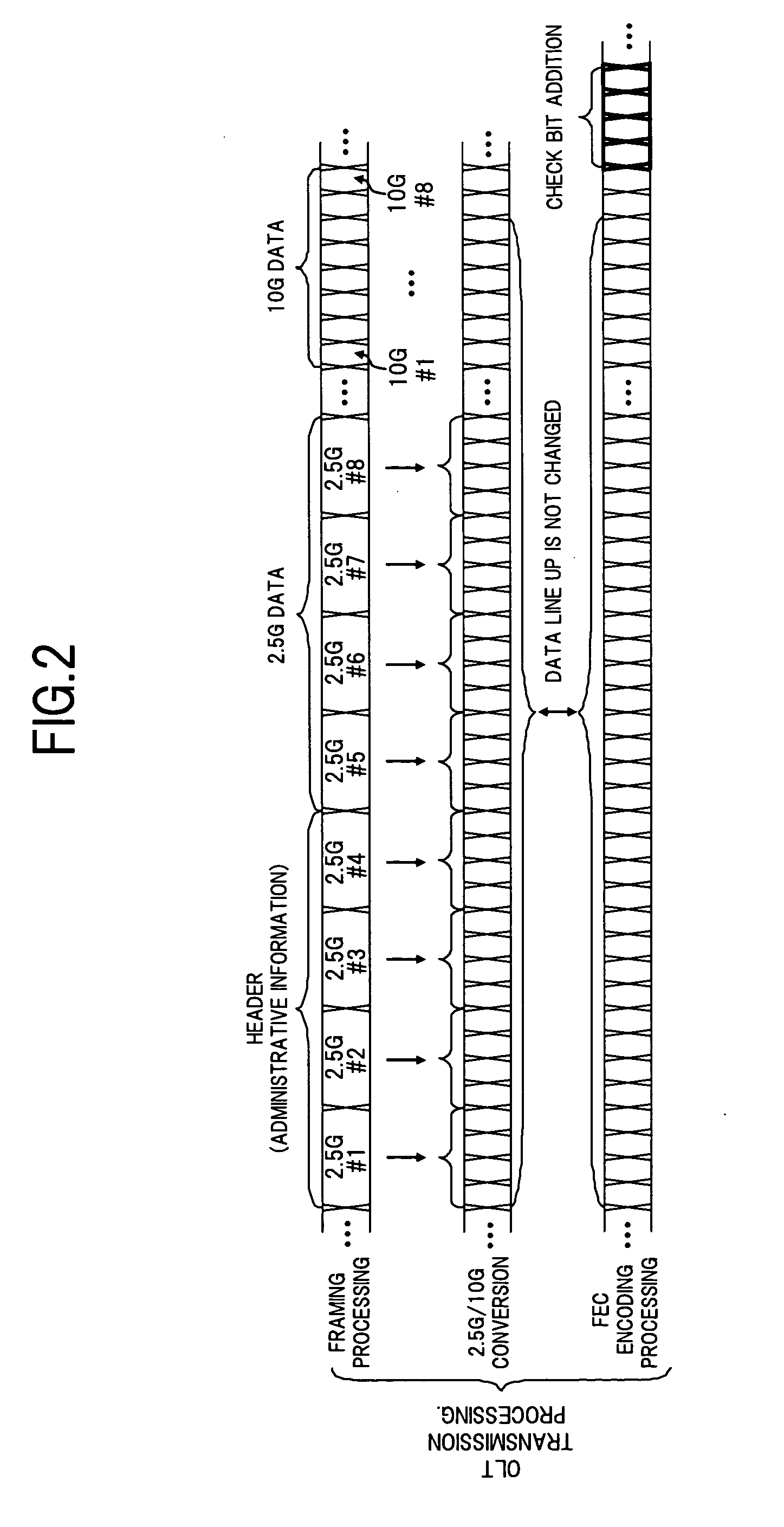
Regarding the passive optical network (PON) system of the present invention, in an OLT, data of different bit rates is framed, and framed data rows are subjected to FEC encoding processing without changing the line up of the data, and a check bit is added to the end of the frame, and an optical signal that has been modulated in accordance with the data row to which the check bit has been added is transmitted to the optical transmission line. Then in an ONU that corresponds to a high speed bit rate to which an optical signal from the OLT has been applied via a power splitter, forward error correction of the reception data is performed. As a result in a PON system in which data of different bit rates coexist, the minimum reception rate of a high speed ONU can be improved without having an influence on a low speed ONU.

Description

BACKGROUND OF THE INVENTION[0001]1. Field of the Invention[0002]The present invention relates to an optical network system the adopts a passive optical network (PON) in which data of different bit rates coexist, and a method of data transmission in the passive optical network.[0003]2. Description of the Related Art[0004]Currently as a subscriber loop optical fiber network system in which premises such as general households are the object, there is known for example a system in which an optical line terminal (station) provided on an aggregated station arranged on a telephone station or the like, and an optical network unit arranged on a plurality of subscriber households, are connected by a transmission line using an optical fiber. Amongst these, a configuration that branches an optical signal transmitted from an aggregated station to an optical transmission line into a plurality of optical signals by a power splitter being a passive element, and connects the optical network unit of ...

Claims


Application Information

Patent Timeline
Patent Type & Authority Applications(United States)
IPC IPC(8): H04B10/20H04B10/27H04B10/272H04B10/524H04J3/00H04J14/08H04L12/44
CPCH04J3/1694H04L1/0078H04L1/0072H04L1/0041H04B10/272H04L1/0063H04Q11/0067H04Q2011/0086H04B10/27H04J3/00H04L12/44
Inventor SAKAI, YOSHIOMORI, KAZUYUKI
Owner FUJITSU LTD
Learn More