Passive video multiplexing method and apparatus

a video multiplexing and video multiplexing technology, applied in static indicating devices, data switching networks, instruments, etc., can solve problems such as unfavorable network server access, restricted expansion, signal failure, etc., and achieve the effect of unlimited scalability

Inactive Publication Date: 2008-09-09
AVOCENT CORP
View PDF66 Cites 6 Cited by
  • Summary
  • Abstract
  • Description
  • Claims
  • Application Information

AI Technical Summary

Benefits of technology

[0005]Video signals produced by a remote computer are routinely transmitted through a KVM (keyboard, mouse, video) extender to a remote user. In one approach, in order to minimize the number of wires extending between a remote computer / server and the remote user location, horizontal and vertical sync signals as well as mode signals are encoded with the analog video signal.
[0011]Referring now to FIG. 5(which is a blowup of a portion of FIG. 4), there is shown another approach for eliminating cable clutter. The system shown at FIGS. 4 & 5, however, works with specific machines. The propriety cable shown in the figure only comes in certain lengths, and therefore the cable must be constructed to service any computer in the rack. As with the prior approaches, any signal failure disables access to some or all network servers. Furthermore, this approach facilitates only one operator at a time to reach the network servers.
[0018]In the preferred embodiment of the present invention, any number of users can communicate on the Ethernet LAN, and any number of servers can be accessed by any of the users. The preferred embodiment provides unlimited scalability while allowing each user to gain console access to any of the associated servers.

Problems solved by technology

Furthermore, system 30 permits a single operator at a time to reach all the servers, and is further restrictive of expansion to an enterprise wide solution.
As with the prior approaches, any signal failure disables access to some or all network servers.
Beyond this distance, wire extensions for K and M signals become problematic due to inadequate signal rise times caused by cable capacitance.
Furthermore, passive cabling systems become bulky when individual wire connections are provided for every required connection.

Method used


Image

  • Passive video multiplexing method and apparatus
  • Passive video multiplexing method and apparatus
  • Passive video multiplexing method and apparatus

Examples


Embodiment Construction

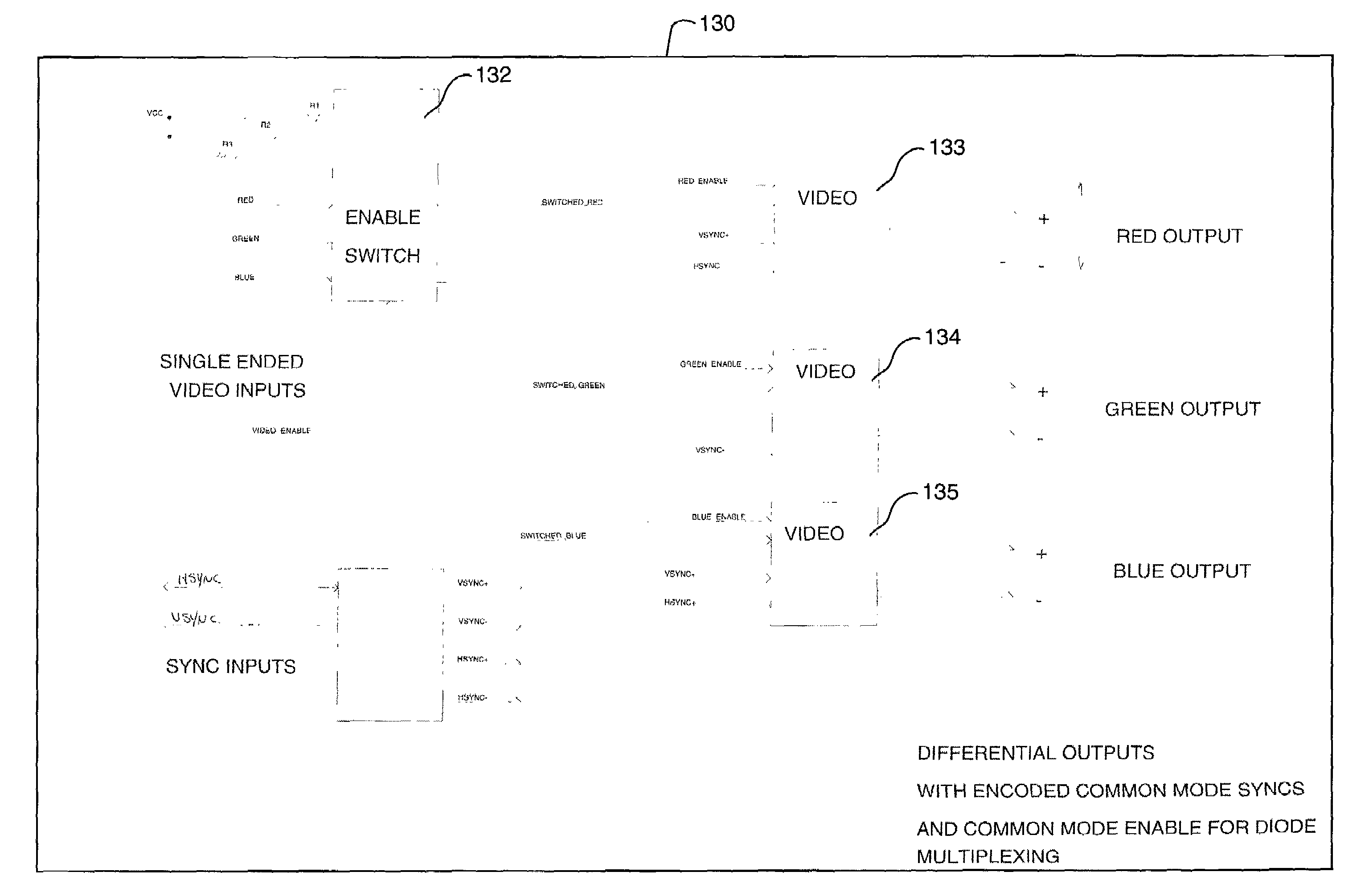
[0045]Referring now to FIG. 12, there is shown a schematic representation of the passive video multiplexing and extension system of the present invention. System 100 includes a corporate LAN 110 to which a remote user 112 is communicatively coupled. In the preferred embodiment, the corporate LAN could be a wide area network (WAN), a packet switching network, such as for example, the Internet, or any other network type. The present invention provides two paths by which the remote user 112 may communicate via LAN 110 to a server 122. One path is via the LAN 110, the Internet Protocol Video (IPV) module 114 to the RCM 116 and then to the server 122. In one embodiment, network servers 122 may be directly connected to RCM 116. In another embodiment, network servers 122 are connected through PEM 120. The second path is directly from the LAN 110 to RCM 116 and then to the server 122.

[0046]When the communication is via the Internet Protocol Video (IPV) module 114, keyboard and mouse (KM) si...


PUM


Abstract

A passive video multiplexing method and apparatus for encoding video synchronization signals within a KVM extension system. A Rack Interface Pod (RIP) is provided for receiving video signals from a network server and providing them to a remote user via a local area network (LAN). The analog signals received by the RIP are transmitted to a Rack Connection Manager (RCM) having video processing logic, a supervisory processor, a KVM switch system, and Ethernet interface circuitry. A plurality of ARI systems are connected to the RCM, and a plurality of network servers, intended to be controlled by the remote user, are connected to each ARI by a respective wiring strip or Pod Expansion Module (PEM). The RCM performs selective switching by sourcing current through a pair of diodes associated with an active channel of the PEM while reverse biasing diodes associated with an inactive channel to select a network server among the plurality of network servers. Switching of video is accomplished without processing the video signals.

Description

PRIORITY TO PRIOR PROVISIONAL APPLICATION[0001]Priority is claimed to Provisional Application Ser. No. 60 / 279,461, filed on Mar. 29, 2001, the entire content of which is hereby incorporated by reference in this application.FIELD OF INVENTION[0002]The present invention relates to a method of connecting to and performing user and administrative functions on remote computer systems. More specifically, it relates to a passive video multiplexing extension system and a method for network based access of those remote computers by users and administrators.BACKGROUND AND SUMMARY OF THE INVENTION[0003]In a typical computer network there are a number of client computers that are coupled via communication links to several network server resources. These resources include, for example, file servers, print servers, modem servers, and CD ROM servers. Each server is usually a stand-alone computer with its own keyboard, video, and mouse monitor (KVM). Each client computer utilizes the functions prov...

Claims


Application Information

Patent Timeline
Patent Type & Authority Patents(United States)
IPC IPC(8): G06F15/16G06F3/02G06FG06F3/00G06F3/14G06F13/00G09G5/00H04L12/24H04L12/56
CPCH04L67/125H04L49/35H04L49/206
Inventor ODYRNA, VICKIRSHTEIN, PHILIP M.THOMAS, CHRISTOPHER L.
Owner AVOCENT CORP
Why Eureka
Try Eureka