Supercharge Your Innovation With Domain-Expert AI Agents!

Hydraulic actuated cavitation chamber with integrated fluid rotation system

a fluid rotation system and hydraulic actuator technology, applied in the direction of positive displacement liquid engine, liquid degasification, separation process, etc., can solve the problems of not revealing any means of stabilizing the movement of the injected bubbles, many aspects of the phenomena have not yet been characterized, etc., to achieve the effect of minimizing the cross-contamination between the cavitation fluid and the hydraulic fluid

Inactive Publication Date: 2008-09-16
BURST ENERGIES INC
View PDF24 Cites 0 Cited by
  • Summary
  • Abstract
  • Description
  • Claims
  • Application Information

AI Technical Summary

Benefits of technology

[0019]In at least one embodiment, an externally mounted motor is magnetically coupled to the impeller and used to rotate the impeller. Impeller rotation can be continuous throughout piston retraction / extension cycling; or initiated after completion of the piston retraction step; or terminated prior to initiating final piston retraction; or terminated prior to initiating piston extension. If impeller rotation is terminated prior to completing piston retraction, preferably the blades of the impeller are positioned to minimize interference between the impeller and the piston, for example by maximizing the distance between the impeller blades and the cavitation piston. Similarly, if impeller rotation is terminated prior to initiating piston extension, preferably the blades of the impeller are positioned to minimize interference between the impeller and the piston, for example by maximizing the distance between the impeller blades and the cavitation piston.
[0021]In at least one embodiment of the invention, cross-contamination between the cavitation fluid and the hydraulic fluid is minimized by interposing a coupling sleeve between the hydraulic driver and the cavitation chamber. Preferably the coupling sleeve is evacuated.

Problems solved by technology

Although it is generally recognized that during the collapse of a cavitating bubble extremely high temperature plasmas are developed, leading to the observed sonoluminescence effect, many aspects of the phenomena have not yet been characterized.
The application does not disclose any means of stabilizing the movement of the injected bubbles or positioning the bubbles within the pressure vessel.
Although a variety of cavitation systems have been designed, typically these systems operate at relatively low pressure, utilize acoustic drivers to cavitate extremely small bubbles, and suffer from a variety of shortcomings due to the inherent instability of the cavitating bubbles.

Method used


Image

  • Hydraulic actuated cavitation chamber with integrated fluid rotation system
  • Hydraulic actuated cavitation chamber with integrated fluid rotation system
  • Hydraulic actuated cavitation chamber with integrated fluid rotation system

Examples


Embodiment Construction

System Overview

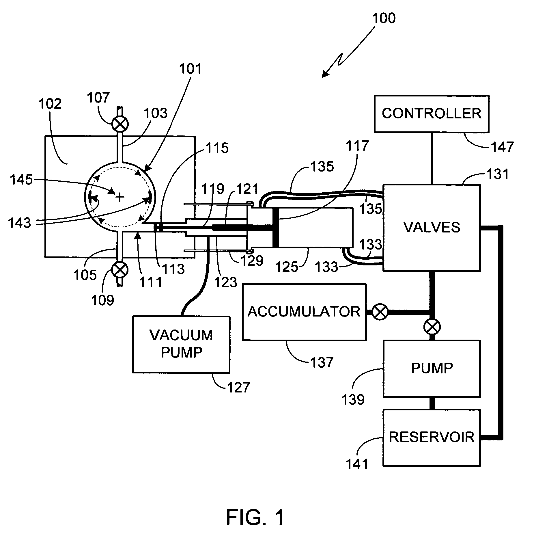
[0045]FIG. 1 is a cross-sectional view of the principal elements of the invention implemented in an exemplary embodiment. The primary component of system 100 is the cavitation chamber 101. Although in the illustrated embodiment cavitation chamber 101 is cylindrically-shaped, it will be appreciated that the invention is not so limited and that cavitation chambers of other configurations (e.g., spherical, conical, cubical, rectangular, etc.) can also be used with the present invention. Chamber 101 must be fabricated to withstand high operating pressures, preferably pressures of at least 1,000 PSI, more preferably pressures of at least 10,000 PSI, and still more preferably pressures of at least 100,000 PSI. Additionally, chamber 101 should be designed to properly seal when evacuated, thus allowing degassing procedures to be performed in situ. Typically chamber 101 is fabricated from multiple pieces which are subsequently held together using brazing, a plurality of bolts,...


PUM

PropertyMeasurementUnit
diameteraaaaaaaaaa
diameteraaaaaaaaaa
outside diameteraaaaaaaaaa

Abstract

A method for initiating cavitation within the fluid within a cavitation chamber is provided. In the cavitation preparatory steps, a hydraulically actuated piston is fully retracted and then the cavitation chamber is isolated. The hydraulic piston is then fully extended after which the chamber is partially opened until a predetermined pressure is obtained. After the chamber is once again isolated, cavities are formed and imploded by retracting and then extending the cavitation piston. At least one impeller, located within the cavitation chamber, is rotated in order to stabilize the cavities.

Description

CROSS-REFERENCES TO RELATED APPLICATIONS[0001]This application is a continuation-in-part of U.S. patent application Ser. No. 11 / 068,080, filed Feb. 28, 2005 and U.S. patent application Ser. No. 11 / 057,347, filed Feb. 14, 2005, which is a continuation-in-part of U.S. patent application Ser. No. 11 / 038,344, filed Jan. 18, 2005, the disclosures of which are incorporated herein by reference for any and all purposes.FIELD OF THE INVENTION[0002]The present invention relates generally to cavitation systems and, more particularly, to a method for cavitating stabilized bubbles within a cavitation chamber using a hydraulic actuated piston.BACKGROUND OF THE INVENTION[0003]Sonoluminescence is a well-known phenomena discovered in the 1930's in which light is generated when a liquid is cavitated. Although a variety of techniques for cavitating the liquid are known (e.g., spark discharge, laser pulse, flowing the liquid through a Venturi tube), one of the most common techniques is through the appl...

Claims


Application Information

Patent Timeline
Patent Type & Authority Patents(United States)
IPC IPC(8): B01F11/00
CPCB01J19/008C02F1/34B01J19/18C02F1/20
Inventor TESSIEN, ROSS ALAN
Owner BURST ENERGIES INC
Features
  • R&D
  • Intellectual Property
  • Life Sciences
  • Materials
  • Tech Scout
  • Unparalleled Data Quality
  • Higher Quality Content
  • 60% Fewer Hallucinations
Learn More