Rotary connector device

a technology of rotary connectors and connectors, applied in the direction of current collectors, rotary current collectors, electrical appliances, etc., can solve the problems of wrong operation of associated electrical equipment, and achieve the effects of preventing short circuits, facilitating installation, and simplifying and space-saving design

Active Publication Date: 2008-09-16
YAZAKI CORP
View PDF10 Cites 16 Cited by
  • Summary
  • Abstract
  • Description
  • Claims
  • Application Information

AI Technical Summary

Benefits of technology

[0010]With the foregoing in view, it is an object of this invention to provide a rotary connector device in which even when a plurality of flat harnesses are installed or arranged in a superposed manner, the short-circuiting between the flat harnesses can be positively prevented upon breakage of the flat harnesses due to their interference with respective guide walls.
[0017]According to one aspect of the invention, even if the flat harnesses should be damaged when the flat harnesses are pulled by an excessive pulling force to abut hard against distal ends of the respective guide portions or if the flat harnesses should be worn as a result of interference with the guide portions, the damaged portions of the flat harnesses are spaced from each other, and therefore there is no risk of short-circuiting between the flat harnesses, and wrong operations of associated electrical equipments, auxiliary equipments, etc., due to the short-circuiting are prevented.
[0018]According to one aspect of the invention, the flat harnesses are installed in such a manner that they are superposed together in the direction of the thickness thereof, and the flat harnesses are guided along the respective guide portions, and are separated from each other by the guide portions. With this construction, even when the plurality of guide portions are provided, the space formed by the covers will not increase, so that the structure can be formed into a simplified and space-saving design.
[0019]According to one aspect of the invention, the guide portions are formed integrally with the respective wall portions disposed respectively in contiguous relation to the outer peripheral wall and the inner peripheral wall, and the other guide portions are formed respectively at the regions spaced from the wall portions in the direction of extending of the wall portions. With this arrangement, the flat harnesses, superposed together, are installed along the wall portions, and can be smoothly introduced one by one into the inside of the covers via the respective guide portions without a bending action, etc., thereby ensuring the durability of the flat harnesses and the reliability of the power supply.

Problems solved by technology

In this case, particularly when this contact pressure is excessive, there has been a fear that the two flat harnesses 75 are broken or cut, so that the short-circuiting between the two flat harnesses 75 occurs, thereby causing wrong operations of associated electrical equipments, etc.

Method used


Image

  • Rotary connector device
  • Rotary connector device
  • Rotary connector device

Examples


Embodiment Construction

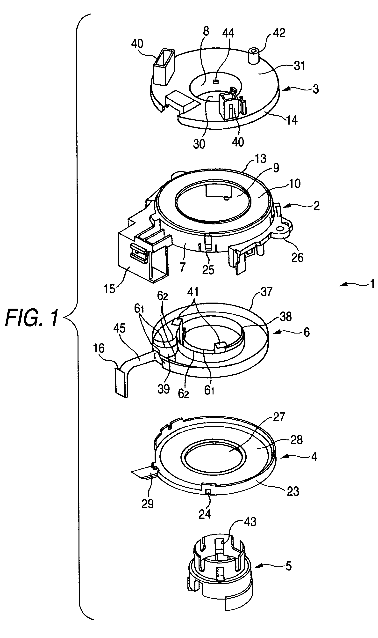
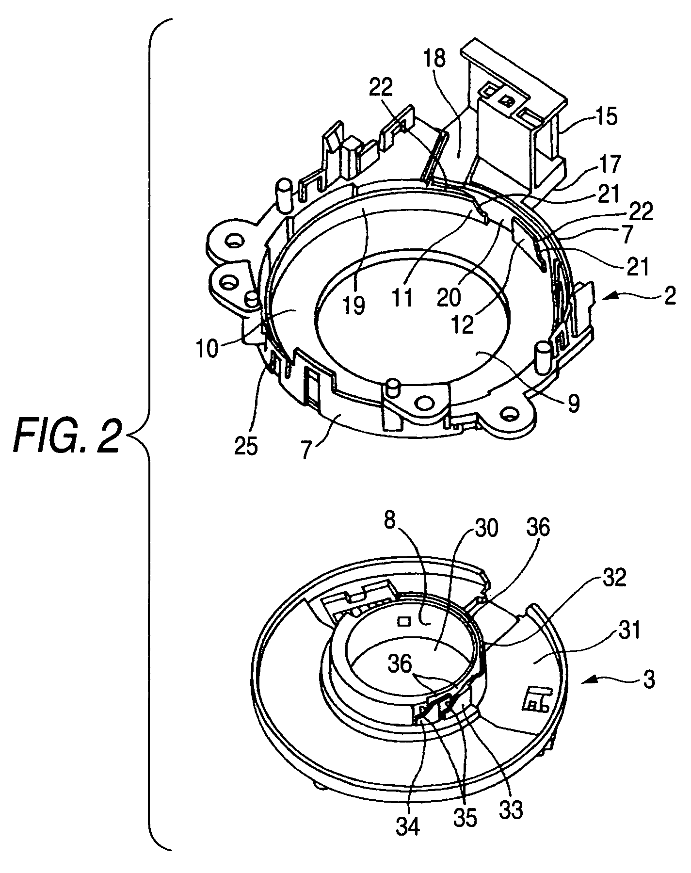
[0025]FIGS. 1 to 3 show one preferred embodiment of a rotary connector device of the present invention.

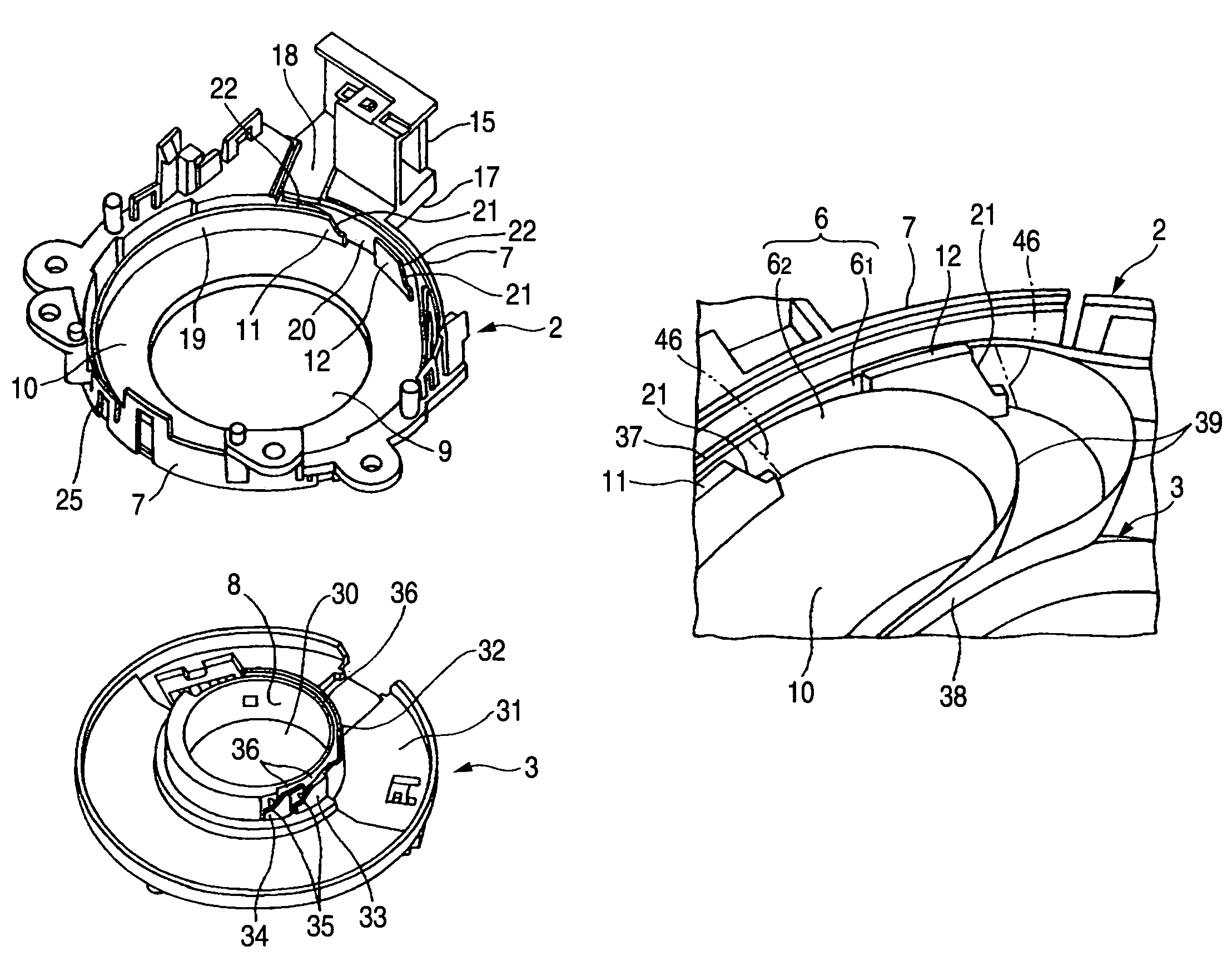
[0026]As shown in FIG. 1 (which is a view as seen from the front side), this rotary connector device 1 comprises a fixed cover (first cover) 2, a rotary cover (second cover) 3, a fixed lid 4, a rotary tube 5, and two flexible flat harnesses 6 which are superposed together, and are received in a generally spirally-wound condition in an annular space formed by the fixed cover 2, the rotary cover 3 and the fixed lid 4. Each of the fixed cover 2, the rotary cover 3, the fixed lid 4 and the rotary tube 5 is made of a synthetic resin. The rotary connector device 1 has a feature that there are provided two guide walls 11 and 12 which cause the two flat harnesses 6 (61 and 62) to independently (or separately) pass respectively to the outer peripheral wall (7)-side of the fixed cover 2 and the inner peripheral wall (8)-side of the rotary cover 3, the two guide walls 11 and 12 being spaced f...


PUM


Abstract

A rotary connector device includes one cover having an outer peripheral wall, the other cover having an inner peripheral wall, and a plurality of flat harnesses which are received in a generally annular shape within a space formed by the two covers, and are rotated and bent in accordance with a rotational motion of one of the two covers. There are provided a plurality of guide portions for guiding the plurality of flat harnesses along the outer peripheral wall and / or the inner peripheral wall independently of each other. The plurality of guide portions are spaced from each other in a harness longitudinal direction. The plurality of guide portions are formed respectively at wall portions, extending respectively in contiguous relation to the outer peripheral wall and the inner peripheral wall in peripheral directions thereof, and regions spaced respectively from the wall portions in directions of extending of the wall portions.

Description

BACKGROUND OF THE INVENTION[0001]1. Field of the Invention[0002]This invention relates to a rotary connector device which is provided, for example, around a steering of an automobile so as to effect a power supply, etc., while absorbing the rotation of the steering by bending and rotating flat harnesses.[0003]2. Related Art[0004]FIG. 4 shows one conventional rotary connector device (see JP-A-10-64646 Publication).[0005]This rotary connector device 61 is provided in the vicinity of a steering (steering wheel) 62, and comprises an annular rotary cover 64 fixed to a steering shaft 63, an annular fixed cover 65 which is disposed around the outer periphery of the steering shaft 63, and is fixed to a combination switch 69, and a flexible flat harness 67 which is disposed in a generally spirally-wound condition within an annular (doughnut-shaped) space 66 formed by the two covers 64 and 65.[0006]Rollers 68 are rotatably provided within the annular space 66, and the flat harness 67 is circu...

Claims


Application Information

Patent Timeline
Patent Type & Authority Patents(United States)
IPC IPC(8): H01R3/00
CPCH01R35/025
Inventor MITSUI, TAKAHIRO
Owner YAZAKI CORP
Why Eureka
Try Eureka