

Metallized sled for communication plug
- Summary
- Abstract
- Description
- Claims
- Application Information
AI Technical Summary
Benefits of technology
Problems solved by technology
Method used
Image

Examples
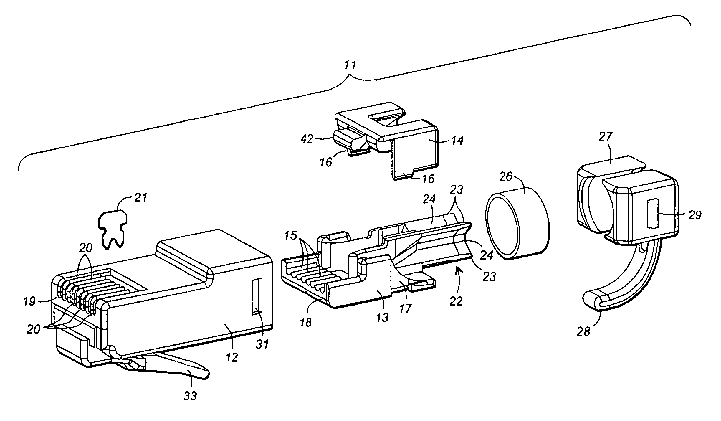
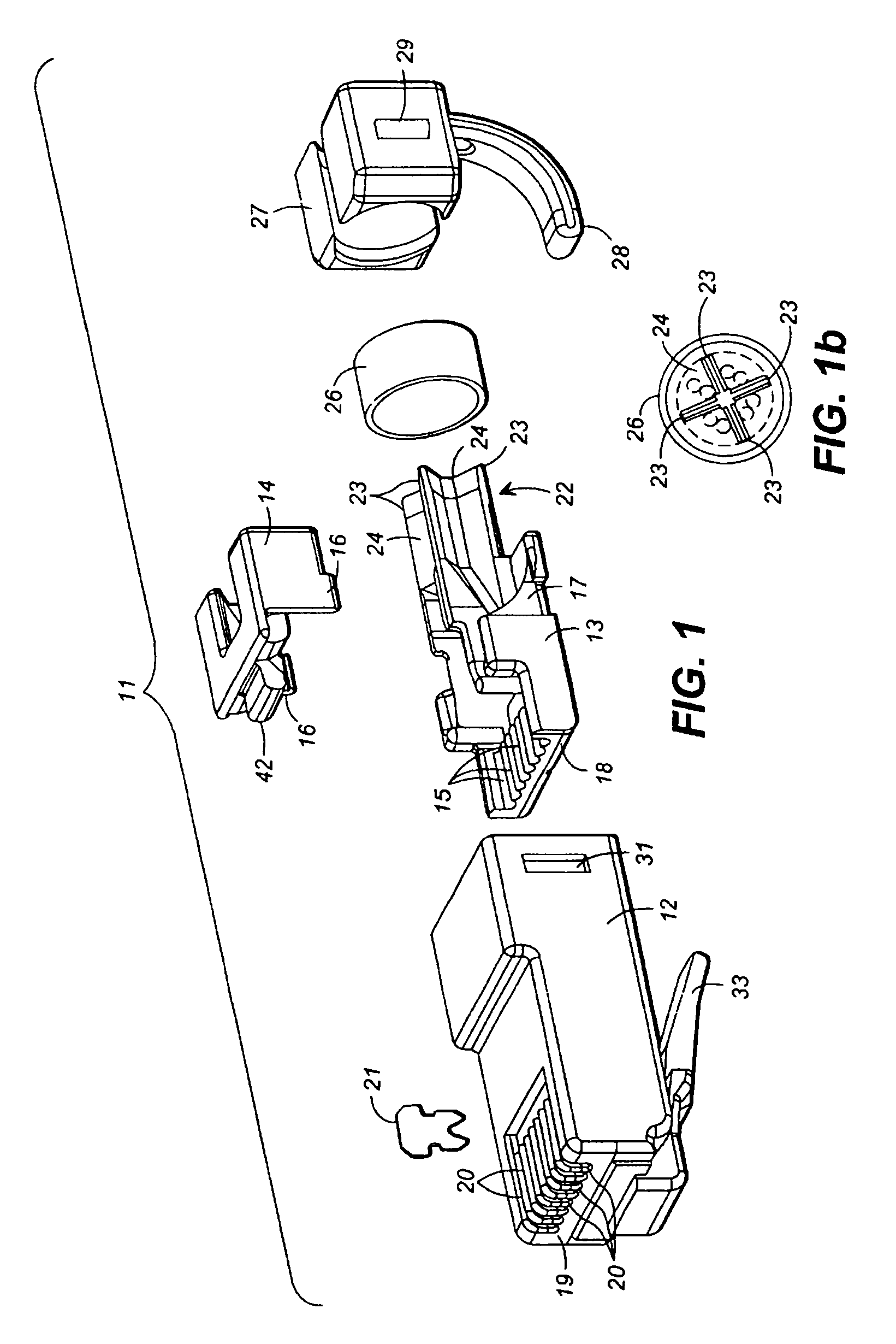
first embodiment
[0066]By the present invention, the conductor organizing sled 13 has been constructed to minimize the variation in NEXT induced between pairs 1 and 3 in the plug due to these variations introduced during the assembly process. In a first embodiment, the conductor organizing sled 13 is first formed of a dielectric material, such as plastic. Next, a portion of the sled 13 in the area of the septa 23 is plated with a conductive material, such as metal. The plating may be performed by a process, such as a vacuum metallizing procedure.
[0067]FIG. 8 is a table showing the measured NEXT between pairs 1 and 2, pairs 1 and 3, and pairs 1 and 4, occurring within a sample of eighteen plugs constructed in accordance with the first embodiment of the present invention. The septa area 23 of the sled 13 was coated with metal layers of stainless steel and copper, totaling approximately five microns in thickness. Although stainless steel and copper were used as the conductive layers in the test batch o...
second embodiment
[0070]As can be seen in FIG. 9, the maximum NEXT measured between pairs 1 and 3 in the plug sample was 14.41 mV, the minimum was 13.36 mV, and average was 14.02 mV (again Magnitude values are also provided in the table, wherein the magnitude value is stated in decibels (dB) and is equal to log10 of the mV value times (−20)). Most importantly, the standard deviation for the measured NEXT between pairs 1 and 3 in the present invention was 0.28 mV. This is again a twenty percent reduction in the standard deviation of 0.35 mV, which corresponds to the plugs produced in accordance with the background art. The lower standard deviation means that on average the NEXT introduced in the plug can be more completely canceled by the compensating NEXT designed into the jack.
[0071]FIG. 10 is a table showing the measured NEXT between pairs 1 and 2, pairs 1 and 3, and pairs 1 and 4, occurring within a plug constructed in accordance with a variation of the second embodiment of the present invention. ...
PUM
 Abstract
Description
Claims
Application Information