Shielded cable connecting structure

a shielded cable and connecting structure technology, applied in the direction of coupling device connection, contact member penetrating/cutting insulation/cable strand, electrical apparatus, etc., can solve the problems of poor operation efficiency, decrease in the number of fine wires, and decrease in the capacity

Inactive Publication Date: 2008-10-07
YAZAKI CORP
View PDF3 Cites 51 Cited by
  • Summary
  • Abstract
  • Description
  • Claims
  • Application Information

AI Technical Summary

Benefits of technology

[0006]This invention has been made in view of the above circumstances, and an object of the invention is to provide a shielded cable connecting structure in which a good operation efficiency can be achieved, and a connecting path of a braided wire can be positively secured.
[0015]In the invention of the above Paragraph 1), the braided wire of the shielded cable is connected to the press-contacting portion or the press-clamping portion, and the spacer connected to the braided wire is connected to the connecting member body, so that a connecting path of the braided wire is formed with a large current-carrying capacity. Therefore, the braided wire, while kept braided around the inner sheath, is electrically connected to the connecting member body without being gathered or twisted. Therefore, a good operation efficiency can be achieved, and the connecting path of the braided wire can be positively secured.
[0021]In the invention of the above Paragraph 4), the spacer can be connected to the braided wire merely by inserting the spacer between the inner sheath and the braided wire, and therefore the operation for connecting the spacer to the braided wire can be carried out easily, so that the operation efficiency can be further enhanced. In this case, preferably, the spacer is so shaped as to be easily inserted between the inner sheath and the braided wire.
[0024]The shielded cable connecting structures of the present invention can solve problems that the operation efficiency is not good because of the need for the gathering or twisting operation and that the reliability against a disturbance is low, and therefore there can be achieved advantages that the good operation efficiency can be achieved and that the grounding path of the braided wire can be positively secured.

Problems solved by technology

However, in the related shielded cable connecting structure disclosed in the JP-A-8-340615, the operation for gathering the exposed braided wires 102 together (that is, a so-called twisting operation) is difficult, and therefore the braided wires 102 (each composed of woven fine wires) become loose, depending on the degree of skill, so that the number of the fine wires decreases, or the capacity decreases.
Thus, the efficiency of the operation is not good, and it is difficult to enhance the productivity by achieving the automated operation.
Considering this with respect to the structure of JP-A-8-340615, the areas of non-shielded portions (where the conductor is not covered with the braided wire over the entire periphery thereof increase as a result of gathering the braided wires together, so that there is a fear that the reliability against the disturbance is not satisfactory.

Method used


Image

  • Shielded cable connecting structure
  • Shielded cable connecting structure
  • Shielded cable connecting structure

Examples


first embodiment

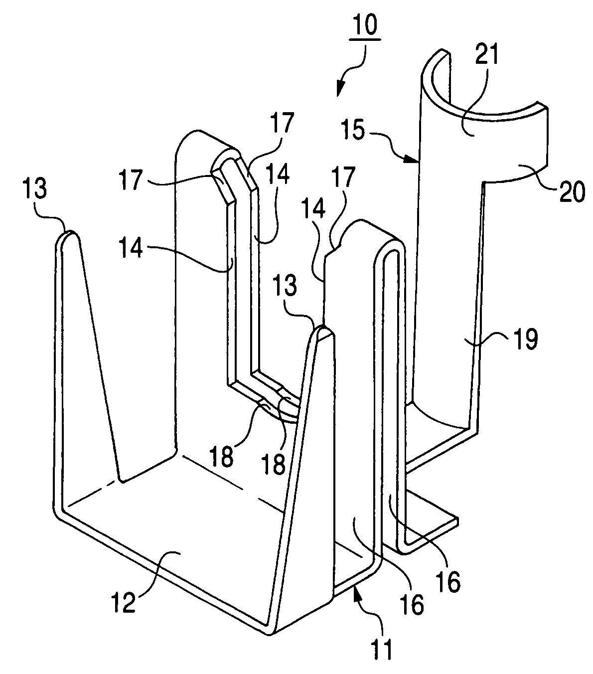
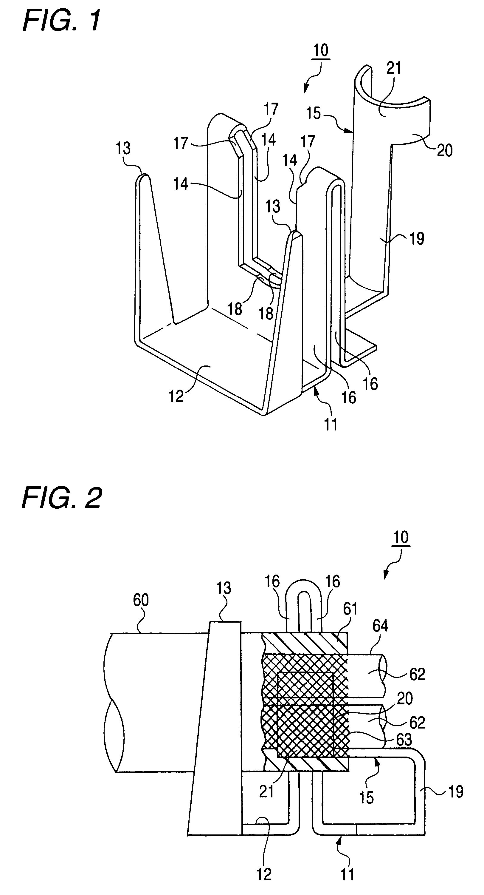
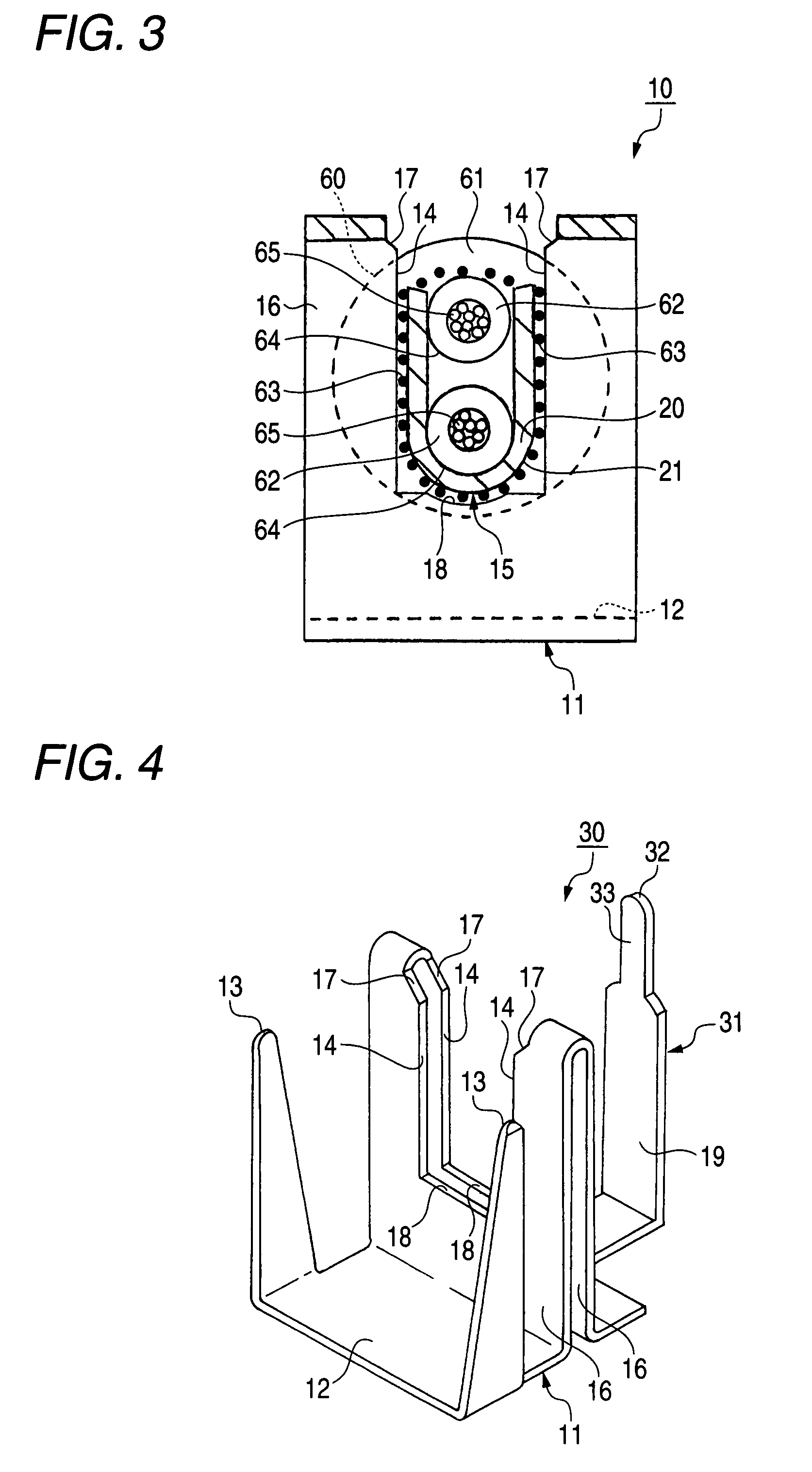
[0044]First, a first embodiment of a shielded cable connecting structure of the invention will be described with reference to FIGS. 1 to 3. FIG. 1 is a perspective view of a shielded cable connecting jig used in the first embodiment of the shielded cable connecting structure of the invention, showing its appearance, FIG. 2 is a partly-broken, front-elevational view showing a condition in which a shielded cable is connected to the shielded cable connecting jig of FIG. 1, and FIG. 3 is a cross-sectional view around the shielded cable of FIG. 2.

[0045]As shown in FIG. 1, the shielded cable connecting jig 10, used in the first embodiment of the shielded cable connecting structure of the invention, includes a connecting member body 11 having a bottom plate 12, a pair of press-fastening portions 13 and 13 formed on and extending upwardly respectively from opposite side edges of the bottom plate 12 at one end portion of the connecting member body 11, a pair of press-contacting portions 14 a...

second embodiment

[0057]Next, a second embodiment of a shielded cable connecting structure of the invention will be described with reference to FIGS. 4 to 6. FIG. 4 is a perspective view of a shielded cable connecting jig used in the second embodiment of the shielded cable connecting structure of the invention, showing its appearance, FIG. 5 is a partly-broken, front-elevational view showing a condition in which a shielded cable is connected to the shielded cable connecting jig of FIG. 4, and FIG. 6 is a cross-sectional view around the shielded cable of FIG. 5. In the following embodiments including this second embodiment, those constituent elements identical or similar in function to those of the first embodiment will be designated by identical or like reference numerals, respectively, and detail explanation thereof will be simplified or omitted.

[0058]As shown in FIG. 4, the shielded cable connecting jig 30, used in the second embodiment of the shielded cable connecting structure of the invention, i...

third embodiment

[0066]Next, a third embodiment of a shielded cable connecting structure of the invention will be described with reference to FIGS. 7 to 10. FIG. 7 is a perspective view of a shielded cable connecting jig used in the third embodiment of the shielded cable connecting structure of the invention, showing its appearance, FIG. 8 is a perspective view showing the manner of connecting a shielded cable to the shielded cable connecting jig of FIG. 7, FIG. 9 is a perspective view showing a condition in which the shielded cable is connected to the connecting jig of FIG. 8, and FIG. 10 is a cross-sectional view around the shielded cable of FIG. 9.

[0067]As shown in FIG. 7, the shielded cable connecting jig 40, used in the third embodiment of the shielded cable connecting structure of the invention, includes a connecting member body 11 having a bottom plate 12, and a pair of press-fastening portions 13 and 13 formed on and extending upwardly respectively from opposite side edges of the bottom plat...


PUM


Abstract

A shielded cable connecting structure for connecting a shielded cable, the shielded cable including an electric wire portion which has a conductor and an inner sheath covering the conductor, a braided wire braided around the inner sheath, and an outer sheath covering the braided wire, the shielded cable connecting structure includes a connecting member. The connecting member includes a connecting main body, a press-fastening portion which press-fastens at least part of the shielded cable, a connecting portion which connects to the braided wire, and a spacer which connects to the braided wire. The spacer increases a contact pressure of the braided wire with the connecting portion.

Description

BACKGROUND OF THE INVENTION[0001]This invention relates to a shielded cable connecting structure used for connecting a braided wire incorporated in a shielded cable.[0002]There is known a related shielded cable connecting structure in which insulating sheaths of shielded cables are removed to thereby expose respective braided wires, and these braided wires are twisted, and then are press-fastened by barrels (see, for example, JP-A-8-340615 (FIG. 1)).[0003]In the shielded cable connecting structure disclosed in JP-A-8-340615, the insulating sheaths 101 of the shielded cables 100 are removed to thereby expose the braided wires 102, and these braided wires 102 are gathered together, and then the shielded cables are press-fastened together by barrels 103, and the braided wires are press-fastened to a drain wire 104 by barrels 105 spaced apart from the barrels 103, as shown in FIG. 17.[0004]However, in the related shielded cable connecting structure disclosed in the JP-A-8-340615, the op...

Claims


Application Information

Patent Timeline
Patent Type & Authority Patents(United States)
IPC IPC(8): H01R4/24
CPCH01R4/2454H01R9/034H01R4/185H01R13/65914
Inventor SAKAGUCHI, TADAHISAENDO, TAKAYOSHI
Owner YAZAKI CORP
Why Eureka
Try Eureka