Measuring device for the amperometric measurement of test strips

a technology of amperometric measurement and measuring device, which is applied in the direction of material testing goods, chemical methods analysis, immunoassays, etc., can solve the problems of high work tool cost and the inability to make the measuring device suitable, and achieve the effect of simplifying the installation of the strip receiver, reducing labor costs, and reducing labor costs

Inactive Publication Date: 2008-10-07
LRE RELAIS & ELECTRONICS GMBH
View PDF3 Cites 2 Cited by
  • Summary
  • Abstract
  • Description
  • Claims
  • Application Information

AI Technical Summary

Benefits of technology

[0008]To match the measuring device to different test strips it is sufficient if the strip receiver as such is changed and put into the device housing. This can be done at a very much lower cost and with much less effort. The unitary separate housing of the strip receiver has, moreover, the advantage that the danger of contamination of the measuring device by the test strips is substantially reduced. The penetration of test fluids into the measuring device can be substantially eliminated.
[0009]To simplify the installation of the strip receiver into the measuring device and its connection with the evaluation and control circuit, it is advantageous if the housing of the strip receiver has on its outer side holding elements for holding it to the board carrying the evaluation and control circuit. For example, the housing can be so designed, that it is insertable into a recess of the board and so that it has guide elements on its outer side for guiding the housing on the edges of the board recess.
[0010]The making of the housing of the strip receiver can be considerably simplified if the housing has two parts connectable with one another with a separation plane which runs through the strip receiver parallel to the strip support surface. Therefore, parts easily removable from their molds can be made without undercuts, between which parts the first internal contact elements can be laid before the two parts are connected with one another, for example by a snap fit with one another.
[0011]The external contact elements are advantageously formed as contact springs which can come into contact with their opposing contact elements formed by conductor paths on the circuit board. The external contact elements can be soldered to their opposing contact elements or they can lie with only mechanical spring tension on their opposing contact elements, which latter case simplifies the exchange of the strip receiver housings, so that one and the same measuring device can easily be reequipped by the user for the processing of different test strips.
[0013]Preferably, at least one further contact element is also provided which is contactable with one of the contact surfaces of the test strip serving for data communication. The strip receiver is preferably so formed that a test strip located in the strip receiver can be moistened with the liquid to be investigated. In this way one avoids the user coming into contact with a moistened test strip when he inserts it into a strip receiver. To avoid having the user take hold of the test strip upon its removal from the measuring device, in accordance with the invention, a test strip release mechanism is provided in the housing of the strip receiver. This release mechanism preferably includes a release element and an actuating element operable from the outside of the housing, which actuating element upon its actuation causes the release element to lift the first, internal, contact springs which urge the test strip against the strip support surface, so that with an associated appropriate orienting of the measuring device the test strip can fall downwardly out of the test strip receiver, for example into a waste container.

Problems solved by technology

This conception has the disadvantage that it is relatively inflexible, so that the measuring device can be made suitable for different customer desires only at considerable expense.
This results in high work tool costs for the making of the housings.

Method used


Image

  • Measuring device for the amperometric measurement of test strips
  • Measuring device for the amperometric measurement of test strips
  • Measuring device for the amperometric measurement of test strips

Examples


Embodiment Construction

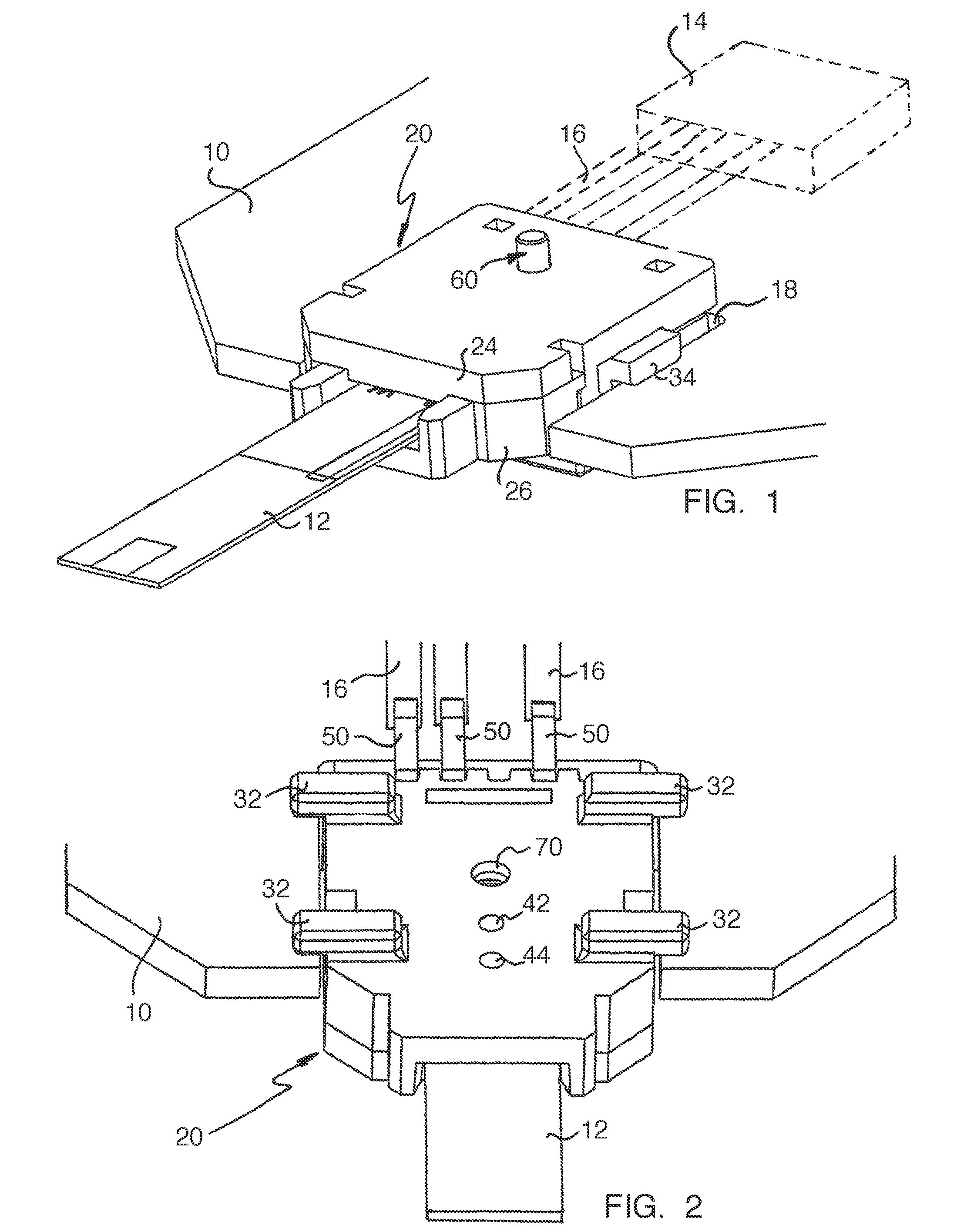
[0023]In FIG. 1, a circuit board is shown at 10, which circuit board is designed for arrangement in the housing of a measuring device for the amperometric measurement of test strips such as the one shown at 12. Since the measuring device can be made in ways known in themselves, the housing of the measuring device is not illustrated here. The circuit board 10 carries an evaluation and control circuit, which is indicated by a processor 14 and conductor pads 16 shown in broken lines.

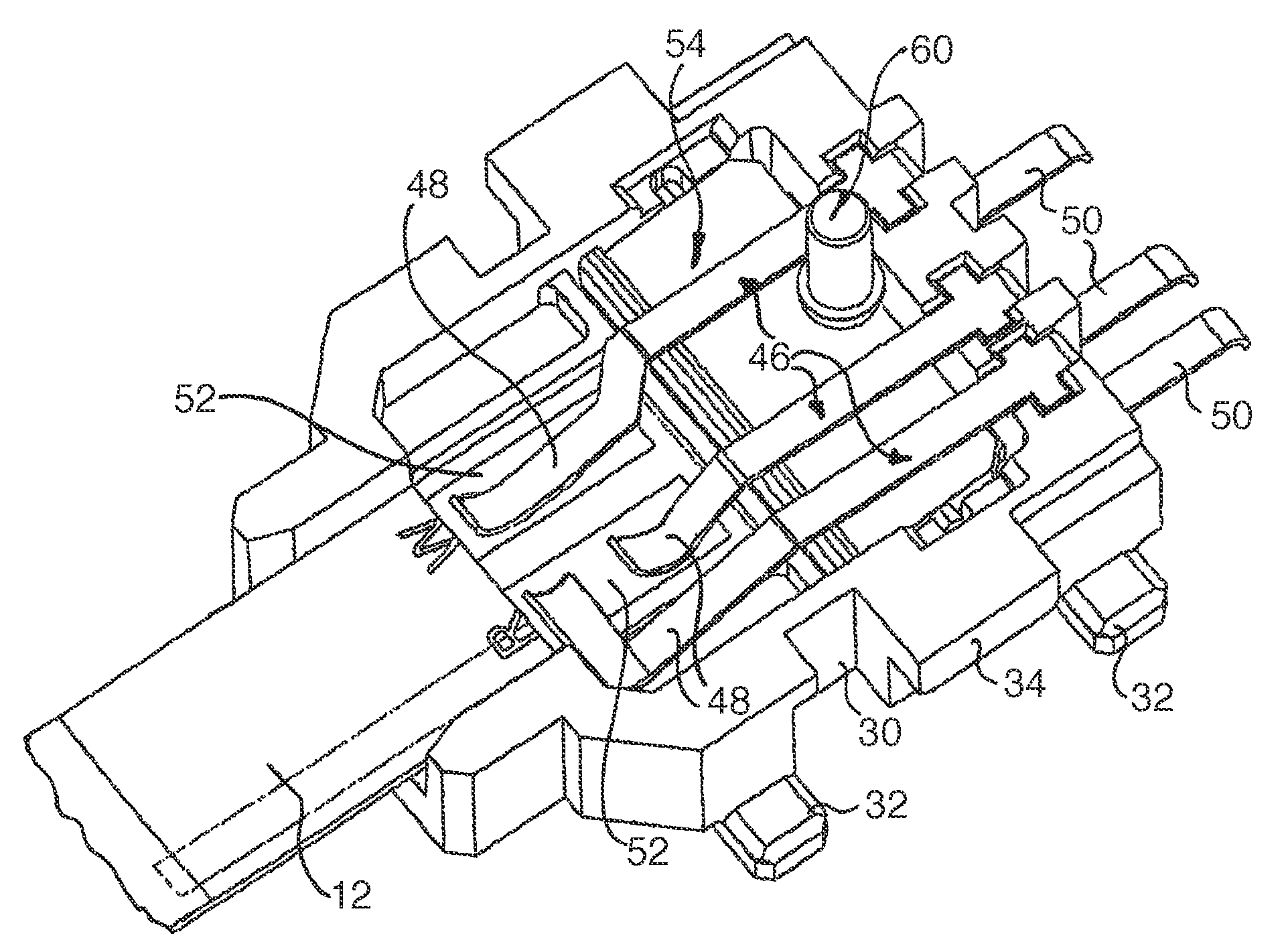
[0024]At the end facing the viewer, the circuit board 10 has a rectangular recess 18 into which is inserted a strip receiver, indicated generally at 20, for the test strips 12, which receiver will now be described further in more detail.

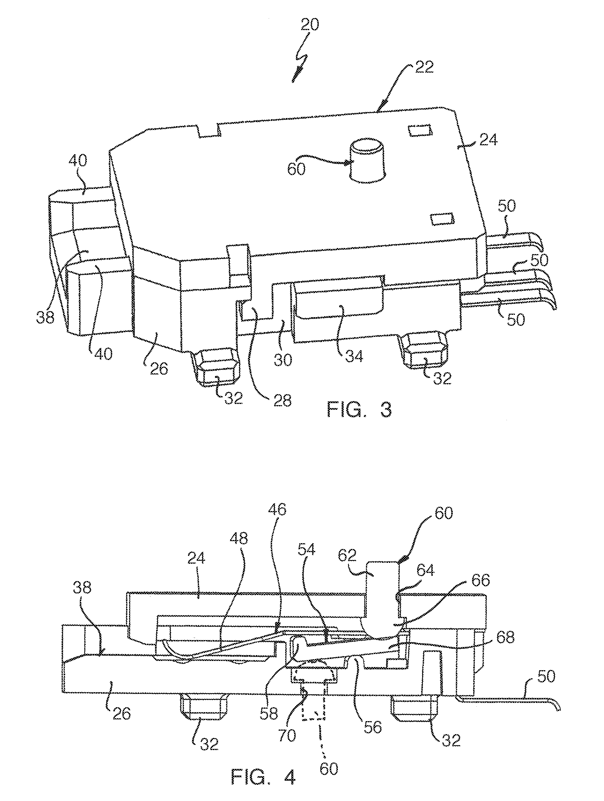
[0025]The strip receiver includes a housing 22 with a housing upper part 24 and a housing lower part 26. The two housing parts 24 and 26 are made of plastic material, preferably by way of an injection molding process. On each of the two longitudinal sides of the housing uppe...


PUM

PropertyMeasurementUnit
pressureaaaaaaaaaa
mechanical spring tensionaaaaaaaaaa
widthaaaaaaaaaa

Abstract

A measuring device for the amperometric measurement of test strips 12, each having a test field moistenable by a liquid to be investigated and having measuring electrodes associated with the test field. The device includes at least one test strip receiver 20 for the insertion of a test strip 12, first contact elements arranged in the region of the strip receiver 20 for contacting the measuring electrodes of a test strip 12 located in the strip receiver 20, and an evaluation and control circuit. The strip receiver 20 is formed with a separate unitary housing which on its external side has second external contact elements 50 electrically connected with the first internal contact elements. The external contact elements 50 are designed for contacting opposite contact elements 16 connected with the evaluation and control circuit.

Description

CROSS REFERENCE TO RELATED APPLICATION[0001]This application claims priority from German Patent Application No. 10 2006 02469.0 filed May 26, 2006, the entire disclosure of which is incorporated herewith by reference.BACKGROUND OF THE INVENTION[0002]1. Field of the Invention[0003]The invention concerns a measuring device for the amperometric measurement of test strips each of which has a test field moistenable by a liquid to be investigated and measuring electrodes associated with the test field, which device includes at least one strip receiver for the insertion of a test strip, first contact elements arranged in the region of the test strip receiver for contacting the measuring electrodes of a test strip located in the strip receiver, and a evaluation and control circuit.[0004]2. Prior Art[0005]Known measuring devices of the above-mentioned kind usually have a plastic material housing in which the strip receiver is formed as well as a circuit board receivable in the housing with t...

Claims


Application Information

Patent Timeline
Patent Type & Authority Patents(United States)
IPC IPC(8): G01N21/00
CPCG01N27/404Y10T436/144444
Inventor POLLMANN, NORBERTHEIDER, WOLFGANGSIRIS, GENRICH
Owner LRE RELAIS & ELECTRONICS GMBH
Why Eureka
Try Eureka