Multi-telescope imaging system utilizing a single common image sensor

a multi-telescope imaging and sensor technology, applied in the field of multi-telescope imaging systems utilizing a single common image sensor, can solve the problems of expensive optical train and sensor components, and achieve the effect of reducing the envelope size, reducing the cost, and facilitating the registration and calibration of images

Active Publication Date: 2008-10-07
RAYTHEON CO
View PDF14 Cites 4 Cited by
  • Summary
  • Abstract
  • Description
  • Claims
  • Application Information

AI Technical Summary

Benefits of technology

[0006]The present approach provides an imaging system having two or more telescopes. The cost, weight, and envelope size of the imaging system are reduced as compared with conventional multi-telescope imaging systems. Achieving registration and calibration of the images are easier as well. The present approach is applicable to imaging systems for spacecraft and other applications.
[0008]In this approach, both telescopes image onto a single sensor. The shutters are opened alternatingly so that only one image reaches the sensor at any moment. A shutter controller is preferably provided to alternatingly open and close the first-telescope shutter and the second-telescope shutter. The first-telescope shutter is closed when the second-telescope shutter is open, and the second-telescope shutter is closed when the first-telescope shutter is open. The shutters are preferably positioned at an aperture stop to maximize the efficiency and minimize the size of the shutter.
[0010]As an additional feature, the backscan-stabilization mirror may be made pivotable about two axes lying in the plane of the planar backscan-stabilization mirror. The backscan-stabilization-mirror controller is operable to pivot the planar backscan-stabilization mirror responsive to a random movement of the telescope relative to the scene. The random movement may be sensed by an accelerometer or other device that is part of the backscan-stabilization-mirror controller, and the backscan stabilization mirror is controlled to move oppositely to the sensed movement. This embodiment of the backscan-stabilization mirror achieves stabilization of the image against random movements.
[0011]In a preferred embodiment, each of the first telescope and the second telescope is an all-reflective telescope. Such an all-reflective telescope includes only mirrors and no lenses in the optical train, which reduces size and weight, avoids chromatic aberrations and restrictions, and avoids radiation sensitivity as compared with refractive telescopes. A preferred form of the all-reflective telescope is an off-axis design that is off-axis in field and / or off-axis in aperture. Most preferably in this embodiment, the all-reflective telescope includes a positive-power primary mirror, a negative-power secondary mirror, a negative-power tertiary mirror, and a positive-power quaternary mirror.
[0013]The present multi-telescope imaging system uses only a single sensor such as a focal plane array. Each of the telescopes images onto the one sensor. The cost of the imaging system is thereby reduced, as compared with a conventional multi-telescope imaging system that uses multiple sensors. The size envelope and consequently the weight are also reduced, important considerations for a structure that must be raised from earth to orbit. Registration and calibration of the images are made easier. Other features and advantages of the present invention will be apparent from the following more detailed description of the preferred embodiment, taken in conjunction with the accompanying drawings, which illustrate, by way of example, the principles of the invention. The scope of the invention is not, however, limited to this preferred embodiment.

Problems solved by technology

Both the optical train and the sensor are expensive components.

Method used


Image

  • Multi-telescope imaging system utilizing a single common image sensor
  • Multi-telescope imaging system utilizing a single common image sensor
  • Multi-telescope imaging system utilizing a single common image sensor

Examples


Embodiment Construction

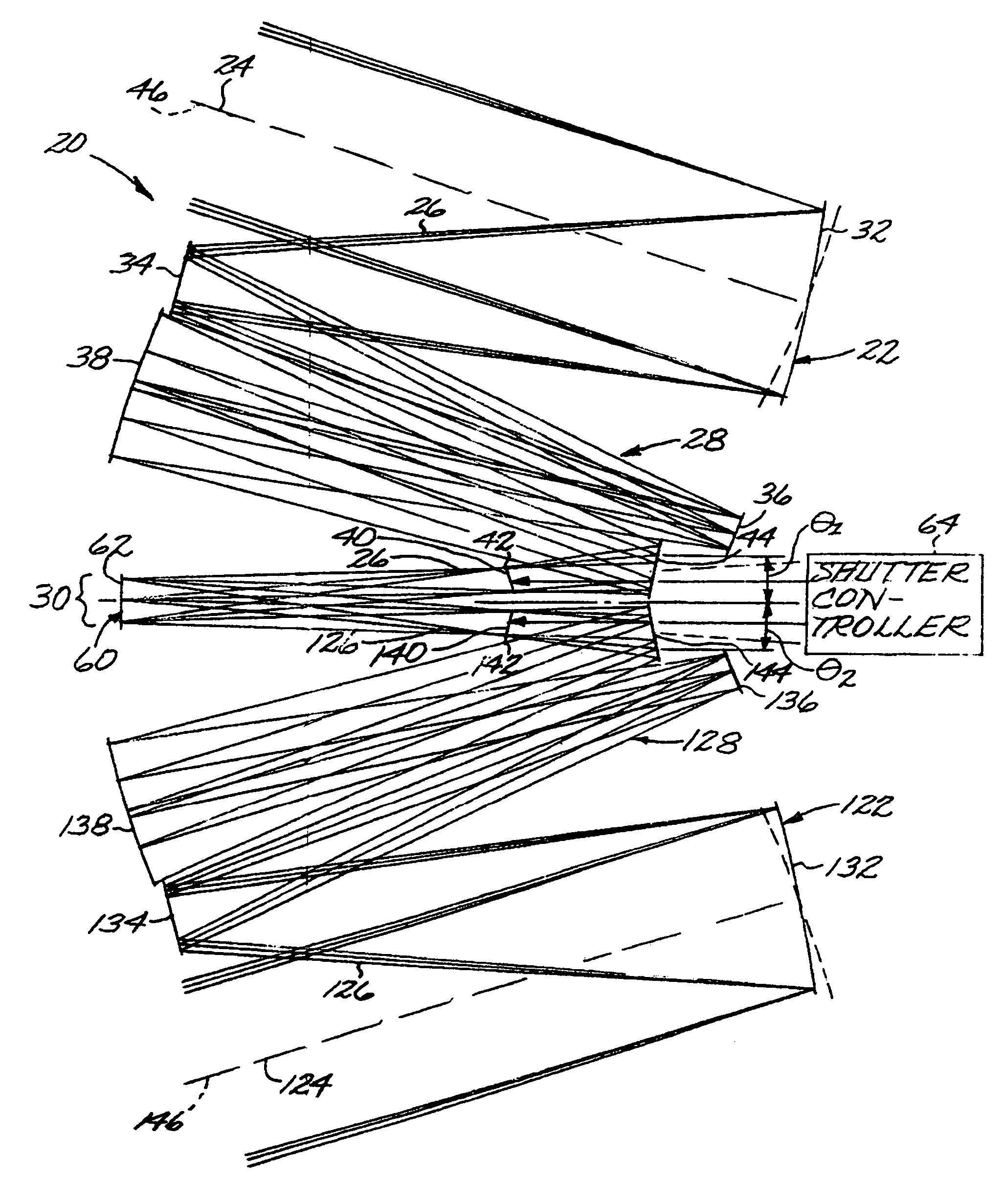
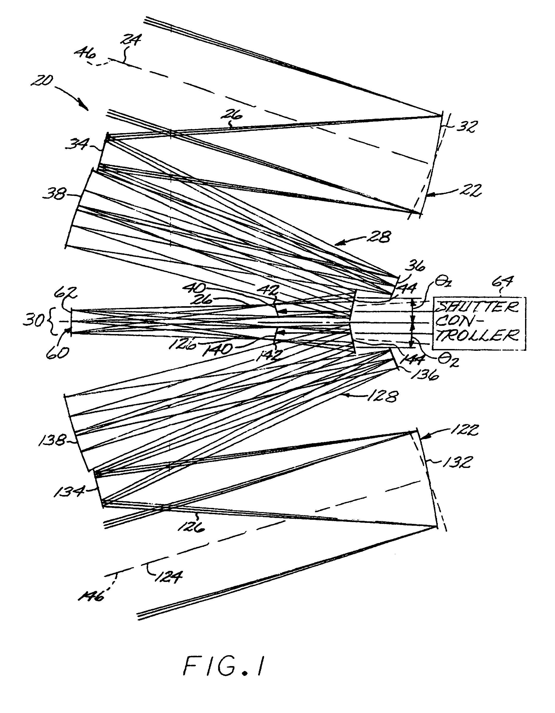
[0025]FIGS. 1 and 2 are ray trace illustrations of a first embodiment of a multi-telescope imaging system 20. FIG. 1 is a side-elevational view, and FIG. 2 is a plan view in which the components are difficult to distinguish because they are stacked overlying each other. Consequently, some of the individual components of FIG. 2 are not numbered. The embodiment of FIGS. 1 and 2 utilizes two telescopes, although there may be three, four, or more telescopes as will be discussed in relation to other embodiments.

[0026]The multi-telescope imaging system 20 includes a first telescope 22 having a first-telescope input line of sight 24 and a first-telescope ray path 26 that passes through an optical train 28 of the first telescope 22 and is ultimately incident upon a focal surface imaging location 30 at a first-telescope angle of incidence θ1, which in this case is a non-normal angle of incidence. Any optical train 28 having an operable combination of reflective and / or refractive optical elem...


PUM


Abstract

A multi-telescope imaging system includes a first telescope and a second telescope, each telescope having an input line of sight, a ray path that is incident upon a focal surface imaging location at a non-normal angle of incidence, and a shutter lying on the ray path. A single common sensor lies at the focal surface imaging location, such that the first-telescope ray path and the second-telescope ray path are alternatingly incident upon the same focal surface imaging location of the sensor. A shutter controller alternatingly opens and closes the two shutters, so that the sensor alternatingly views the scenes imaged by the two telescopes.

Description

[0001]This invention relates to an imaging system and, more particularly, to an imaging system that uses at least two telescopes that image upon the same imaging location of a common sensor.BACKGROUND OF THE INVENTION[0002]For some applications it is useful to image a scene from two angles to obtain a stereoscopic viewing effect or for other reasons. For example, an imaging system in an earth-orbiting satellite spacecraft may include a first telescope aimed toward the scene at a first angle, and a second telescope aimed toward the scene at a second angle. The images from the two telescopes may be used to form a stereoscopic image of the scene, if the two telescopes are aimed at the proper angles. The images may also be used to provide information that a single image cannot, even if not arranged for stereoscopic imaging. For example, a satellite flying from south to north (the scan direction) may use a forward-inclined telescope to image the south side and then the top of a building ...

Claims


Application Information

Patent Timeline
Patent Type & Authority Patents(United States)
IPC IPC(8): G02B23/02
CPCG02B17/0663G02B17/0694G02B26/105
Inventor COOK, LACY G.
Owner RAYTHEON CO
Why Eureka
Try Eureka