Suction opening body and electric cleaner

a technology of suction opening and electric cleaner, which is applied in the direction of suction cleaners, cleaning equipment, domestic applications, etc., can solve the problems of affecting the suction efficiency of sucking dust, pushed dust cannot be efficiently sucked, and dust existing near a wall cannot be sucked, so as to achieve efficient sucking dust

Inactive Publication Date: 2008-10-14
TOSHIBA TEC KK
View PDF27 Cites 2 Cited by
  • Summary
  • Abstract
  • Description
  • Claims
  • Application Information

AI Technical Summary

Benefits of technology

[0007]The present invention has been made in a view of the aforementioned problems, and accordingly, it is an object of the present invention to provide a suction inlet unit and an electric vacuum cleaner which can prevent dust on a cleaning surface from being pushed forwards when the suction inlet unit is being moved forward, and can efficiently suck dust near a wall.
[0012]Furthermore, the suction inlet unit according to the present invention is characterized in that it comprises a suction inlet main body which includes a suction chamber having a bottom suction inlet and a front suction inlet formed continuously with the bottom suction inlet; a rotary cleaning body provided rotating in the suction chamber and having a cleaning member; and the adjusting mechanism for adjusting an opening area size of the front suction inlet. In other words, when a front portion of the suction inlet main body is pushed contacting with a wall or furniture etc, the adjusting mechanism adjusts the opening area size of the front suction inlet by decreasing the opening area so that at least one part of the cleaning member of the rotary cleaning body can protrude ahead of the suction inlet main body through the front suction inlet.
[0014]As already described above, according to the present invention, the cover is configured so that the opening area of the front inlet of the suction inlet main body are decreased when the suction inlet unit is pushed forward, causing the suction inlet main body to contact with a wall or furniture, thus the dust on the cleaning surface is prevented from being pushed forwards and the dust near the wall are also sucked in efficiently by a strong suction force.

Problems solved by technology

Thus, there arises such a problem that the forwardly pushed dust can not be efficiently sucked, which seriously affects suction efficiency in sucking the dust.
Furthermore, there is a bottom wall section 4B formed between an anterior edge 2a of the bottom suction inlet 2 and a front surface of the suction inlet main body 4, thus there arises another problem that the dust existing near a wall can not be sucked.

Method used


Image

  • Suction opening body and electric cleaner
  • Suction opening body and electric cleaner
  • Suction opening body and electric cleaner

Examples


Embodiment Construction

[0026]Hereinafter, modes for carrying out a suction inlet unit according to the present invention and an electric vacuum cleaner with the suction inlet unit disposed thereon will be explained in detail with reference to the drawings.

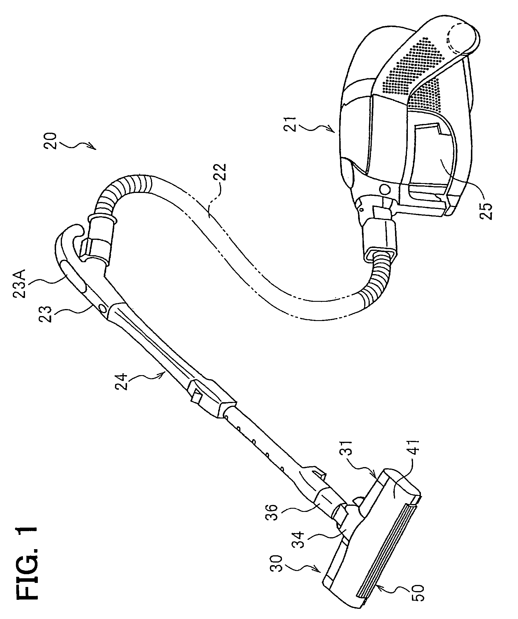
[0027]FIG. 1 shows the electric vacuum cleaner 20 to which the suction inlet unit 30 of the present invention is applied. The electric vacuum cleaner 20 comprises a vacuum cleaner main body 21, a hose 22 with one end thereof detachably connected to the vacuum cleaner main body 21 and a hand-held operating pipe 23 provided at the other end thereof, and an extension tube 24 detachably connected to the hand-held operating pipe 23. The suction inlet unit 30 is detachably connected to a leading end portion of the extension tube 24.

[0028]An operating section 23A is provided on the hand-held operation pipe 23. On the operating section 23A, there are provided operating switches and buttons (not shown) for operating the electric vacuum cleaner.

[0029]In the vacuum...


PUM


Abstract

A suction inlet unit comprises a suction inlet main body having a bottom suction inlet, a front suction inlet formed continuously with said bottom suction inlet in the front of said suction inlet main body, and a cover for covering the front suction inlet. The cover, provided at the suction inlet main body to be movable by an adjusting mechanism for adjusting an opening area size of said front suction inlet to a determined area, is configured to decrease the opening area of the front suction inlet when a front portion of the cover is contacted by a wall or furniture.

Description

[0001]This application is a U.S. National Phase Application under 35 USC 371 of International Application PCT / JP2004 / 009795 filed Jul. 9, 2004.TECHNICAL FIELD[0002]The present invention relates to a suction inlet unit having a bottom suction inlet and a front suction inlet, and an electric vacuum cleaner including the suction inlet unit.BACKGROUND ART[0003]Conventionally, a suction inlet unit having a structure as shown in FIG. 10 is disposed on an electric vacuum cleaner (see, for example, Japan Patent laid-Open No. H11-206,635).[0004]The suction inlet unit 1 includes a suction inlet main body 4 provided with a suction chamber 3 having a bottom suction inlet 2 in a bottom surface 1A, and a rotary cleaning body 5 which is provided rotating in the suction chamber 3. The rotary cleaning body 5 is rotated counterclockwise (as shown in FIG. 10) by air drawn in from an air-sucking inlet 6 provided in the suction inlet main body 4.[0005]According to the suction inlet unit 1, because dust ...

Claims


Application Information

Patent Timeline
Patent Type & Authority Patents(United States)
IPC IPC(8): A47L9/02A47L5/00A47L9/00A47L9/04
CPCA47L9/02A47L9/0477A47L9/04
Inventor NAITO, JUNJIICHINO, TAKAYUKISUGIYAMA, YOSHITAKA
Owner TOSHIBA TEC KK
Why Eureka
Try Eureka