Ink-jet printer and method of sucking ink from air-discharge cap of ink-jet printer

a technology of air-discharge cap and inkjet printer, which is applied in the field of ink, can solve the problems of air-discharge cap such as the cap is movable against the biasing force, the viscosity of the ink is certain, and the size of the air-discharge cap is increased, so as to achieve the effect of effectively preventing the ink from remaining in the cap and efficient sucking

Inactive Publication Date: 2011-02-01
BROTHER KOGYO KK
View PDF8 Cites 0 Cited by
  • Summary
  • Abstract
  • Description
  • Claims
  • Application Information

AI Technical Summary

Benefits of technology

[0012]In the above-identified background, the present invention has been developed. It is therefore an object of the present invention to solve at least one of the above-identified problems. It is another object of the present invention to provide an ink-jet printer that enjoys a simple construction and / or a reduced size of an arrangement around an air-discharge cap thereof. It is another object of the present invention to provide a method of sucking ink from an air discharge cap of an ink-jet printer and thereby preventing the ink from remaining in the cap.
[0014]In the present ink-jet printer, the air-discharge cap has the bottom wall, the side wall projecting upward from the periphery of the bottom wall and the suction hole, and the air-flow generating device causes the air flow inlet to open at a position distant from the suction hole in the third direction having the first component parallel to the bottom wall of the air-discharge cap, so that when the suction device sucks the air through the suction hole, the air flows from the air flow inlet toward the suction hole in the fourth direction having the second component opposite to the first component of the third direction. Thus, the arrangement around the air-discharge cap can be simplified and reduced in size. For example, the air-flow generating device may comprise at least one projecting portion that projects from at least one side surface of the air-tight-space defining device, at least one hook portion having at least one fitting hole within which the at least one projecting portion is movable, and a biasing device that biases the air-tight-space defining device toward the carriage. In this particular case, when a moving device moves the hook portion toward the carriage, the air-discharge cap can be closely contacted with the carriage. Thus, in this case, the projecting portion of the air-tight-space defining device and the fitting hole of the hook portion cooperate with each other to assure that the cap is movable relative to the carriage. That is, the engagement of the projecting portion of the air-tight-space defining device and the fitting hole of the hook portion is utilized to support the air-discharge cap. Thus, the arrangement around the air-discharge cap can be simplified and reduced in size.
[0016]In the present method, first, the air-discharge cap is closely contacted with the carriage so as to define the air-tight space, subsequently the air-discharge cap is inclined to provide or form the gap between the cap and the carriage, and then the ink present in the cap is sucked from an ink-suction portion of the cap that is opposite to the gap. Therefore, air is caused to flow from the gap between the cap and the carriage toward the ink suction portion, and the ink is conveyed by the air flow to the ink suction portion. Thus, in the present method, the ink discharged into the air-discharge cap can be efficiently sucked and accordingly the ink can be effectively prevented from remaining in the cap.

Problems solved by technology

However, ink has a certain degree of viscosity and accordingly the ink adhered to the air-discharge cap may not be removed by just applying suction thereto.
However, the arrangement needed to support, with a frame-side member (or a housing), the air-discharge cap such that the cap is movable against the biasing force may be complicated and / or increased in size.

Method used


Image

  • Ink-jet printer and method of sucking ink from air-discharge cap of ink-jet printer
  • Ink-jet printer and method of sucking ink from air-discharge cap of ink-jet printer
  • Ink-jet printer and method of sucking ink from air-discharge cap of ink-jet printer

Examples


first embodiment

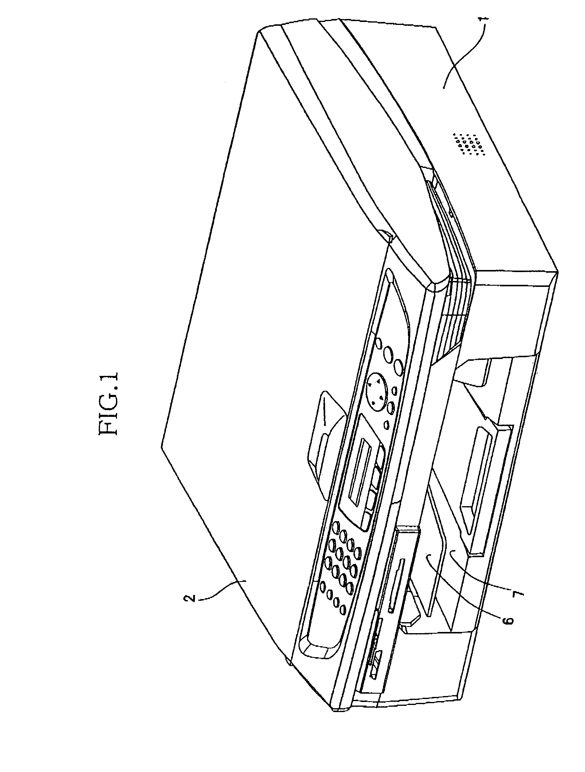
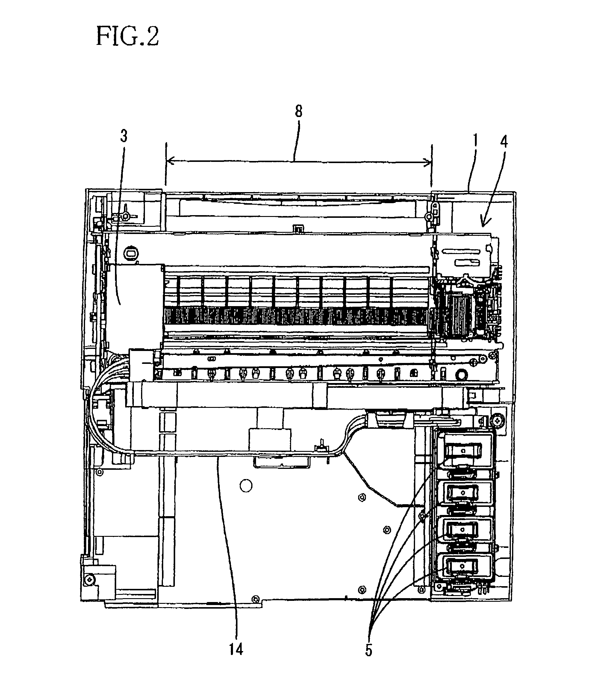
[0040]Hereinafter, there will be described preferred embodiments of the present invention by reference to the drawings. the present invention relates to an ink-jet printer having a printer function, a scanner function, and a copier function. As shown in FIGS. 1 and 2, the ink-jet printer includes a main frame or housing 1, and an original-image reading device 2 that is provided above the housing 1 and serves for the scanner function and the copier function. Below the original-image reading device 2, the housing 1 accommodates a recording-related carriage 3, a maintenance unit 4 that recovers four recording heads 10, described later, from clogging of nozzles thereof, and four ink tanks (i.e., four ink cartridges) 5 that respectively supply four sorts of inks to the four recording heads 10. In a front portion of the housing 1, there are provided a sheet-discharge tray 6 and a sheet-supply tray 7. The carriage 3 reciprocates in opposite directions, i.e., leftward and rightward directio...

second embodiment

[0121]FIGS. 21A and 21B show the present invention. The second embodiment differs from the first embodiment shown in FIGS. 1 through 20, in that the two extending portions 49 of the lift member 41 are replaced with two extending portions 149, the air-discharge cap 40 is replaced with an air-discharge cap 140, the air-discharge-cap holder 48 is replaced with an air-discharge-cap holder 148. In the second embodiment, the two extending portions 149 have respective fitting holes 149a that have respective upper ends at different height position. The air-discharge cap 140 is formed of an elastically deformable material such as a rubber, and has a suction hole 147 formed in a rear end portion of a bottom wall thereof and a first projecting portion 140a projecting from a front end surface of a side wall thereof. The air-discharge-cap holder 148 is formed of a rigid material such as a resin, and has a second projecting portion 148a projecting from a rear end surface of a side wall thereof, a...

third embodiment

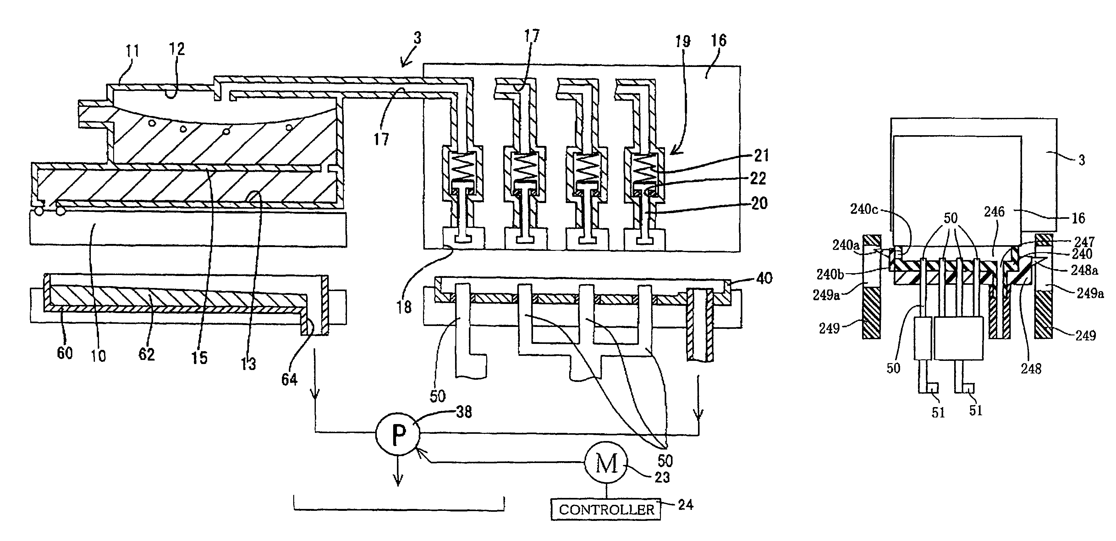
[0122]FIGS. 22A and 22B show the present invention. The third embodiment differs from the first embodiment shown in FIGS. 1 through 20, in that the two extending portions 49 of the lift member 41 are replaced with two extending portions 249, the air-discharge cap 40 is replaced with an air-discharge cap 240, the air-discharge-cap holder 48 is replaced with an air-discharge-cap holder 248. In the third embodiment, the two extending portions 249 have respective fitting holes 249a that have respective upper ends at different height position. The air-discharge cap 240, an opening and closing valve 240b a lower portion of which is fixed to a front surface of a front end portion of a side wall of the air-discharge cap 240, and a first projecting portion 240a projecting from a front surface of the opening and closing valve 240b are all formed of an elastically deformable material such as a rubber, and the air-discharge cap 240 has a suction hole 247 formed in a rear end portion of a bottom...


PUM


Abstract

An ink-jet printer including a carriage carrying recording heads, air collecting chambers, and discharging passages communicating with the respective air collecting chambers; opening and closing valves provided in the respective discharging passages; opening and closing bars which open and close the respective valves; an air discharge cap which has a bottom wall, a side wall, and a suction hole, wherein an upper end surface of the side wall is closely contactable with a lower surface of the carriage to cover respective openings of the discharging passages; a suction device which sucks air through the suction hole; and an air-flow generating device which causes an air flow inlet to open at a position distant from the suction hole, so that when air is sucked through the suction hole, the air flows from the air flow inlet toward the suction hole. An ink sucking method is also provided.

Description

[0001]The present application is based on Japanese Patent Applications No. 2006-166419 and No. 2006-166420 each filed on Jun. 15, 2006, the contents of which are incorporated herein by reference.BACKGROUND OF THE INVENTION[0002]1. Field of the Invention[0003]The present invention relates to an ink-jet printer that ejects, from nozzles thereof, droplets of ink and thereby records an image on a recording medium, and particularly to such an ink-jet printer that can remove air bubbles produced in one or more ink-flow passages and thereby maintain a high recording quality. The present invention also relates to a method of sucking ink that has been discharged into an air-discharge cap of an ink-jet printer when air bubbles are removed through the cap, the ink-jet printer additionally including one or more ink ejection portions (or one or more recording heads) that eject, from nozzles thereof, droplets of ink, and one or more ink-flow passages which supply the ink to the ink-ejection porti...

Claims


Application Information

Patent Timeline
Patent Type & Authority Patents(United States)
IPC IPC(8): B41J2/165
CPCB41J2/16523B41J2/16508
Inventor HIRAKI, NOBUOUMEDA, TAKAICHIROITO, NORITSUGUKAGA, HIKARUSHINDO, TATSUYASUGIYAMA, WATARUNISHIDA, KATSUNORIHIGUCHI, TOMOHISA
Owner BROTHER KOGYO KK
Why Eureka
Try Eureka