Cutting apparatus

a technology of cutting apparatus and cutting fluid, which is applied in the direction of grinding/polishing apparatus, metal working apparatus, manufacturing tools, etc., can solve the problems of difficult to sufficiently remove the cut dust from the water supply to the upper surface of the workpiece is not sufficient, and the upper surface of the workpiece is soiled as a whole, so as to prevent the scattering of cutting fluid containing the cut dust toward the upper surface of the workpi

Active Publication Date: 2019-01-22
DISCO CORP
View PDF9 Cites 0 Cited by
  • Summary
  • Abstract
  • Description
  • Claims
  • Application Information

AI Technical Summary

Benefits of technology

[0008]It is therefore an object of the present invention to provide a cutting apparatus which can reduce the possibility that the cut dust may stick to the workpiece.
[0012]As described above, the cutting apparatus of the present invention includes the blade cover having the bottom portion formed with the slit for allowing projection of a part of the cutting edge of the cutting blade for cutting the upper surface of the workpiece and also includes the cutting fluid supplying means for supplying a cutting fluid to the upper surface of the workpiece on both sides of the slit. Accordingly, the cutting fluid supplied to the workpiece in cutting the workpiece is not directed to the cutting blade covered with the blade cover, so that there is no possibility that the cutting fluid may be scattered by the rotation of the cutting blade.
[0013]Further, the blade cover is formed with the discharge passage having one end communicating with the slit and the other end communicating with the discharge opening connected to the vacuum source. Accordingly, the cutting fluid supplied to the upper surface of the workpiece by the cutting fluid supplying means is attracted to a cutting point where the cutting blade comes into contact with the workpiece by the operation of the vacuum source, thereby performing cooling at this cutting point. At the same time, cut dust generated in cutting the workpiece can be captured by the cutting fluid and immediately discharged from the discharge opening to the outside of the blade cover. Thusly, the cutting fluid containing the cut dust is sucked into the discharge passage and then discharged from the discharge opening, so that it is possible to reduce the possibility that the cut dust may stick to the upper surface of the workpiece.
[0015]The cutting fluid supplying means includes the plural cutting fluid nozzles formed on the bottom portion of the blade cover and arranged so as to extend parallel to the slit on both sides thereof, and also includes the cutting fluid passage having one end connected to the cutting fluid nozzles and the other end connected to the cutting fluid source. Accordingly, it is unnecessary to directly supply the cutting fluid to the cutting blade, but the cutting fluid can be effectively supplied to the cutting point where the cutting blade comes into contact with the workpiece. As a result, scattering of the cutting fluid containing the cut dust toward the upper surface of the workpiece can be prevented and it is therefore possible to prevent that the cut dust may stick to the upper surface of the workpiece.
[0016]Further, the suction opening is formed at one end of the slit on the extension of the discharge passage. Accordingly, even when the amount of flow of the cutting fluid is increased or the cut dust has a large size, the cutting fluid containing the cut dust can be efficiently sucked from the suction opening and then discharged from the discharge opening to the outside of the blade cover.

Problems solved by technology

Accordingly, the cut dust generated in cutting the workpiece is partly captured by the cutting water, and the cutting water containing the cut dust may be scattered onto the workpiece in association with the rotation of the cutting blade, causing a problem such that the upper surface of the workpiece is soiled as a whole.
When the cut dust sticks to the upper surface of the workpiece as mentioned above, it is difficult to sufficiently remove the cut dust from the upper surface of the workpiece even by the use of the cleaning water supplying means mentioned above.
That is, even when the cleaning water is supplied to the upper surface of the workpiece by the cleaning water supplying means, the flow of the cleaning water supplied to the upper surface of the workpiece may be disturbed by the cutting water scattered onto the workpiece, so that there arises a problem such that an insufficiently cleaned area is left on the workpiece and the cut dust on the workpiece cannot be completely removed.

Method used


Image

  • Cutting apparatus
  • Cutting apparatus
  • Cutting apparatus

Examples


Embodiment Construction

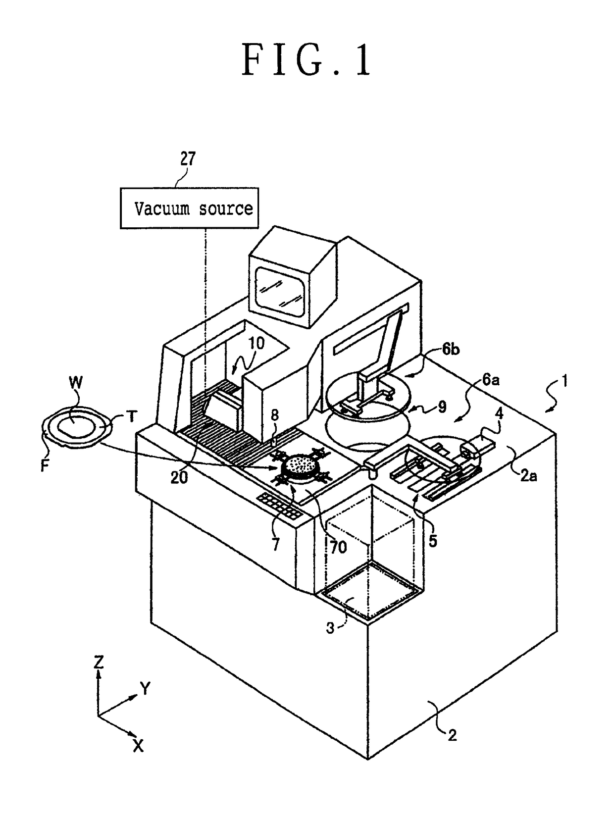
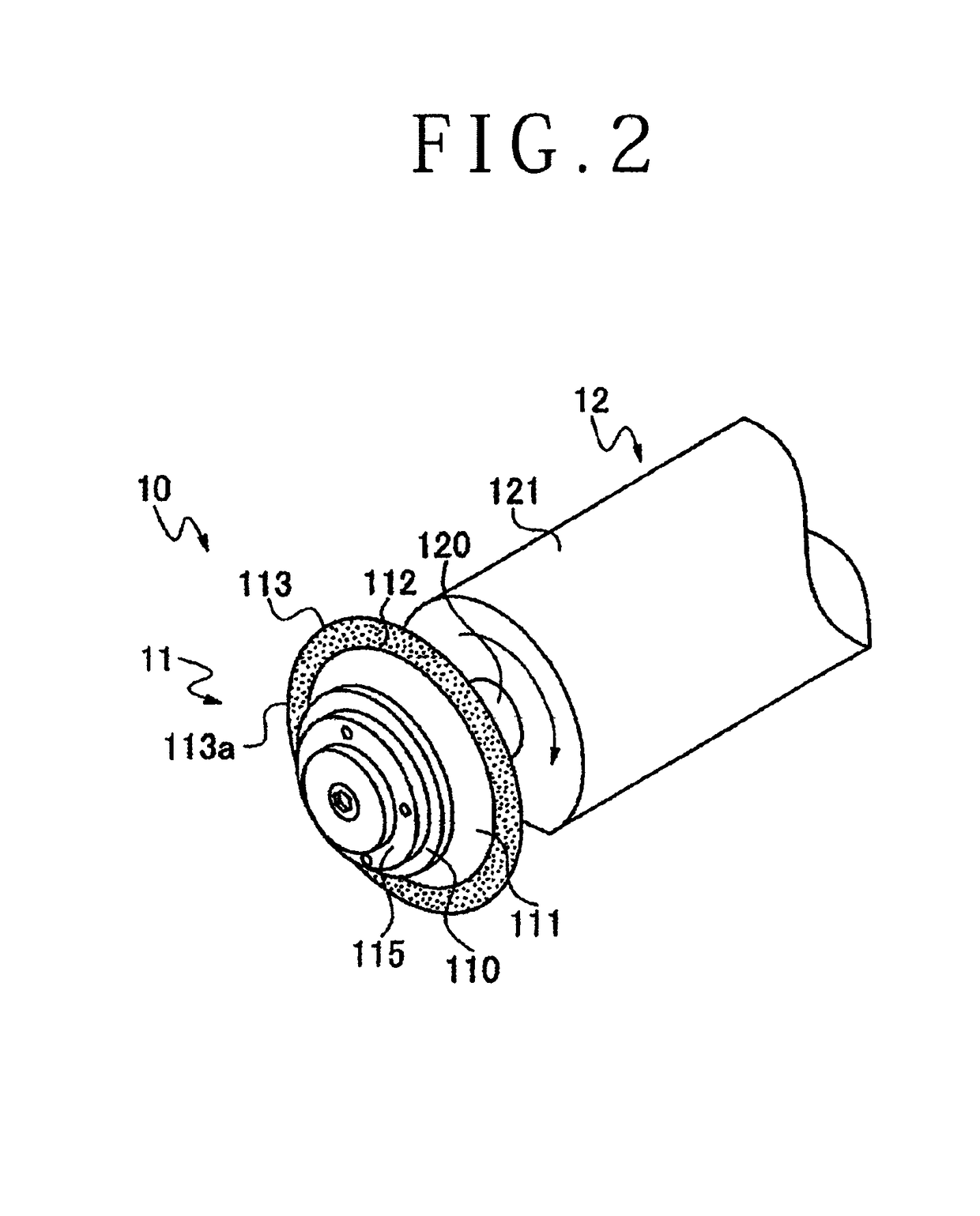
[0027]Referring to FIG. 1, there is shown a cutting apparatus 1 according to a preferred embodiment of the present invention. The cutting apparatus 1 has a unit base 2. A cassette 3 for storing a plurality of workpieces is provided at a front portion of the unit base 2. The unit base 2 has an upper surface 2a, on which there are provided handling means 4 for taking one of the workpieces out of the cassette 3 before cutting and returning the workpiece into the cassette 3 after cutting, a temporary setting area 5 for temporarily setting the workpiece, and holding means 7 for holding the workpiece. There is provided in the vicinity of the cassette 3 first transfer means 6a for transferring the workpiece from the temporary setting area 5 to the holding means 7 before cutting.

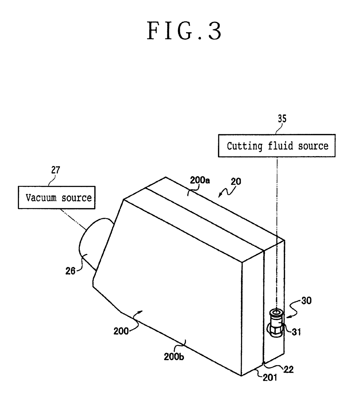
[0028]The holding means 7 is connected to a vacuum source (not shown) and it is accordingly adapted to hold the workpiece under suction. The periphery of the holding means 7 is covered with a moving base 70. The hol...


PUM

PropertyMeasurementUnit
thicknessaaaaaaaaaa
widthaaaaaaaaaa
areasaaaaaaaaaa

Abstract

A cutting apparatus including a holding unit for holding a workpiece, a cutting blade having a peripheral cutting edge for cutting a workpiece, a spindle unit including a spindle for rotating the cutting blade, a blade cover mounted on the spindle unit for covering the cutting blade, the blade cover having a bottom portion formed with a slit for allowing projection of a part of the cutting edge of the cutting blade, and a cutting fluid supplying unit for supplying a cutting fluid to the upper surface of the workpiece on both sides of the slit. The cutting fluid is not directly supplied to the cutting blade, but it is supplied to the upper surface of the workpiece. Accordingly, there is no possibility that the cutting fluid may be scattered by the rotation of the cutting blade.

Description

BACKGROUND OF THE INVENTION[0001]Field of the Invention[0002]The present invention relates to a cutting apparatus having a blade cover.[0003]Description of the Related Art[0004]In a cutting apparatus having a cutting blade for cutting a workpiece, a cutting fluid is supplied to the cutting blade during cutting, so as to remove process heat (cutting heat) generated due to cutting and also remove cut dust (saw dust or sludge) generated in cutting from the upper surface of the workpiece. In the case that the workpiece is a wafer on which imaging devices such as CMOSs and CCDs are formed or a substrate on which optical devices such as filters and optical pickup devices are formed, there is a possibility that the adhesion of cut dust to the devices may cause poor quality of the devices. Accordingly, great importance is placed on the prevention of the adhesion of cut dust to the devices.[0005]Once cut dust sticks to the upper surface of the workpiece and then dries, it is very difficult t...

Claims


Application Information

Patent Timeline
Patent Type & Authority Patents(United States)
IPC IPC(8): B28D5/00B26D7/22B26D7/08B24B55/06B24B55/02B26D7/18B26D1/14
CPCB28D5/0076B24B55/02B24B55/06B26D7/088B26D7/22B28D5/00B26D7/1863Y10T83/207B26D1/14
Inventor GADD, MICHAEL
Owner DISCO CORP
Why Eureka
Try Eureka