Eureka AIR delivers breakthrough ideas for toughest innovation challenges, trusted by R&D personnel around the world.

Door frame apparatus and method for installing a door frame

a door frame and door frame technology, applied in the field of installing a door frame, can solve the problems of door frame which does not allow the door to sit in the finished frame properly, the door frame will not close properly, and the door frame will not install correctly, so as to prevent slippage

Inactive Publication Date: 2008-10-14
TAYLOR ROBERT
View PDF14 Cites 4 Cited by
  • Summary
  • Abstract
  • Description
  • Claims
  • Application Information

AI Technical Summary

Benefits of technology

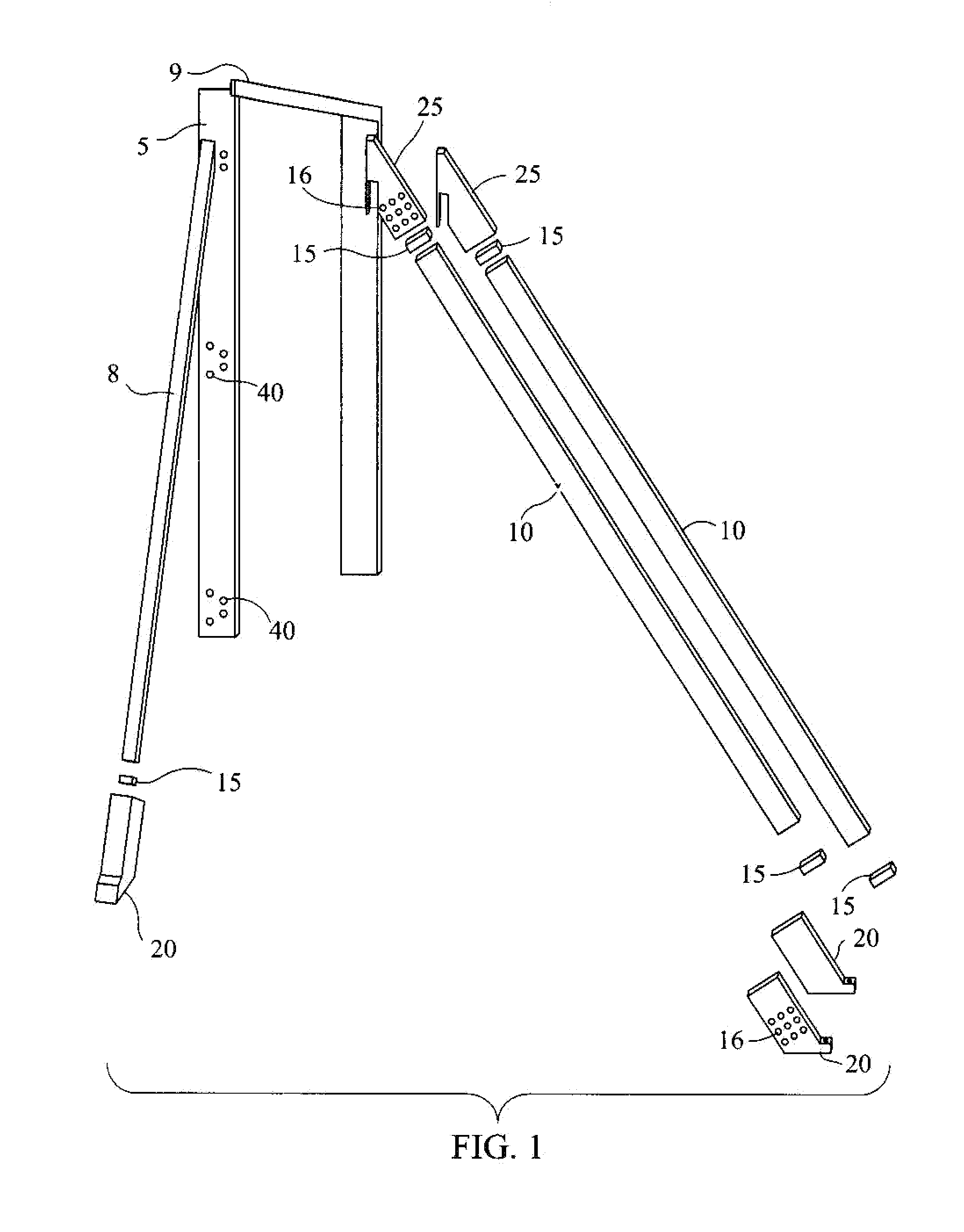
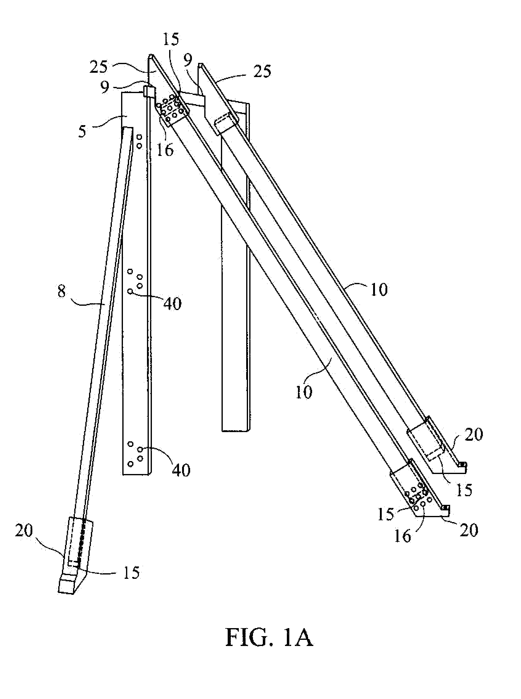
[0015]The extension members are then inserted into the foot brackets. The foot brackets are identical to each other and stops are inserted within the foot brackets to ensure uniform placement of the extension members within the device. Stops are also placed in the two top framing brackets to maintain position of the extension members within the framing members and foot brackets and to prevent slippage.
[0016]Because of the identical dimensions of the foot brackets, framing brackets and extension members, uniform placement of the door within the frame itself is achieved.
[0018]The use of the two extension members and the side member together ensures the true fit of the door frame in all planes.

Problems solved by technology

One of the difficulties when framing a door is to ensure that it is true, level and plumb in all directions.
If the door is not framed correctly initially, it will not close properly when the surrounding structure is complete.
The problem with this arrangement is that if the worker does not measure the distance from the door to the placement point correctly and the pieces are at different distances, even slightly different distances, from the lower edge of the door frame, the door will not install correctly.
However, because of incorrect measurements or inconsistent methods of attaching to the floor, this may produce a door frame which does not allow the door to sit in a finished frame properly.
None of the prior art examples address framing the door in all dimensions and all planes.
Additionally, the method of installation in the other devices is substantially different than the method of truly aligning the door within the space as contemplated by this device.

Method used


Image

  • Door frame apparatus and method for installing a door frame
  • Door frame apparatus and method for installing a door frame
  • Door frame apparatus and method for installing a door frame

Examples


Embodiment Construction

[0027]One of the objects of this device is to ensure that a door is framed within the door opening in all planes. This device will accomplish that result with relative ease and with unique simplicity.

[0028]When this device is used, a door will be frames correctly in all planes. The device can be easily picked up and transported to the next door or the next job site. It will be constructed of durable material such as fiberglass re-enforced plastic (FRP). It is not anticipated that metal will be used because metal is corrosive and heavy.

[0029]Additionally, fiberglass is probably the preferred material because of its lightweight and durable characteristics in addition to its relatively low cost.

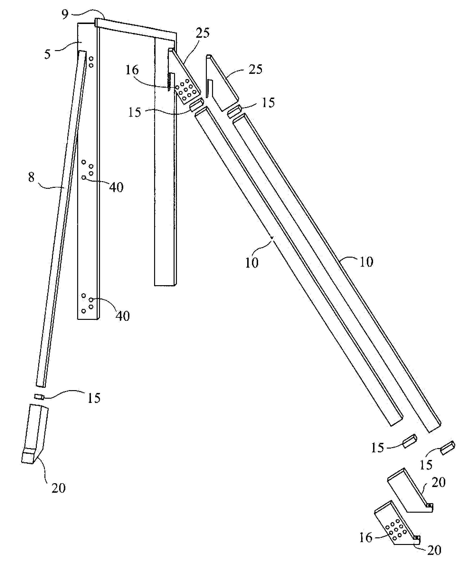
[0030]This device is comprised of two identically shaped top framing brackets 25, each of the top framing brackets is attached via a slot or opening in the top framing bracket 25 to the top of a door frame 5, three foot brackets 20, which also have a slot or opening for the respective extension ...


PUM


Abstract

In order to correctly align a door in a doorway structure, this device has been contemplated. It will be comprised of several identically shaped members that extend from the top of the door jamb to another separate member that is secured to the floor. The use of dual members that extend from the door jamb to the floor aligns the door in one dimension in the doorway but in order to align the door from the side a separate side member will be used.

Description

CROSS REFERENCES TO RELATED APPLICATIONS[0001]Not ApplicableSTATEMENT REGARDING FEDERALLY SPONSORED RESEARCH[0002]Not ApplicableREFERENCE TO APPENDIX[0003]Not ApplicableBACKGROUND OF THE INVENTION[0004]A. Field of the Invention[0005]This relates to installing a door frame so that is aligned within the space in all planes and also the method for framing the door.[0006]B. Prior Art[0007]One of the difficulties when framing a door is to ensure that it is true, level and plumb in all directions. This includes being true and plumb in all planes. If the door is not framed correctly initially, it will not close properly when the surrounding structure is complete.[0008]The usual method to install a door is to first position a piece of wood on the concrete floor. A piece of lumber is then extended from this floor piece to the doorjamb. Often times there are two or more pieces of wood on the floor. The problem with this arrangement is that if the worker does not measure the distance from the ...

Claims


Application Information

Patent Timeline
IPC IPC(8): E04G21/04E04B1/00E04H12/20
CPCE04F21/0007E04F21/0015Y10S269/905
Inventor TAYLOR, ROBERT
Owner TAYLOR ROBERT
Why Eureka
Eureka Blog
Learn More