Pedal assembly support structure for vehicle

a technology for supporting structures and pedal assemblies, which is applied in the direction of mechanical control devices, instruments, tractors, etc., can solve the problems of preventing reliable implementation of the ability to angularly move the pedal lever, applying an impact to the driver's leg, etc., and achieves the effect of effective restrainting the bracket and the guide member, smooth backward movement, and improved reliability

Inactive Publication Date: 2008-10-14
MAZDA MOTOR CORP
View PDF30 Cites 13 Cited by
  • Summary
  • Abstract
  • Description
  • Claims
  • Application Information

AI Technical Summary

Benefits of technology

[0016]Further, the support structure includes the relative shift restricting member. Therefore, even if the direction of collision load input from the dash panel to the bracket in a vehicle collision is inclined to the vehicle front-to-rear direction, the rear end portion of the bracket is restrained from shifting in directions other than the vehicle rearward direction relative to the front end portion of the guide member, so that the bracket moves only in the vehicle rearward direction relative to the guide member. As a result, the bracket dropped out of the guide member moves backward while being guided downward by the guide surface, which ensures the desired capability to angularly move the pedal lever.
[0049]In this case, since the relative shift restricting member comes into point contact with the bracket or the guide member, the bracket or the guide member has only a small friction resistance when the bracket move backward in a vehicle collision. Therefore, the bracket can smoothly disengage from the guide member.

Problems solved by technology

In car collisions, as is often the case, a car cannot be fully stopped even though the driver brakes the car by stepping on a brake pedal for the purpose of avoidance of a collision, resulting in the collision, namely, the car leads to the collision with the brake pedal trod.
As a result, a load of car collision acts on the driver's foot with which the driver has stepped on the brake pedal until immediately before the collision to produce a large kick back, thereby applying an impact to the driver's leg.
This may prevent reliable implementation of a desired capability to angularly move the pedal lever by moving backward the pedal bracket dropped out of the guide member while guiding it downward along the guide surface.

Method used


Image

  • Pedal assembly support structure for vehicle
  • Pedal assembly support structure for vehicle
  • Pedal assembly support structure for vehicle

Examples


first embodiment

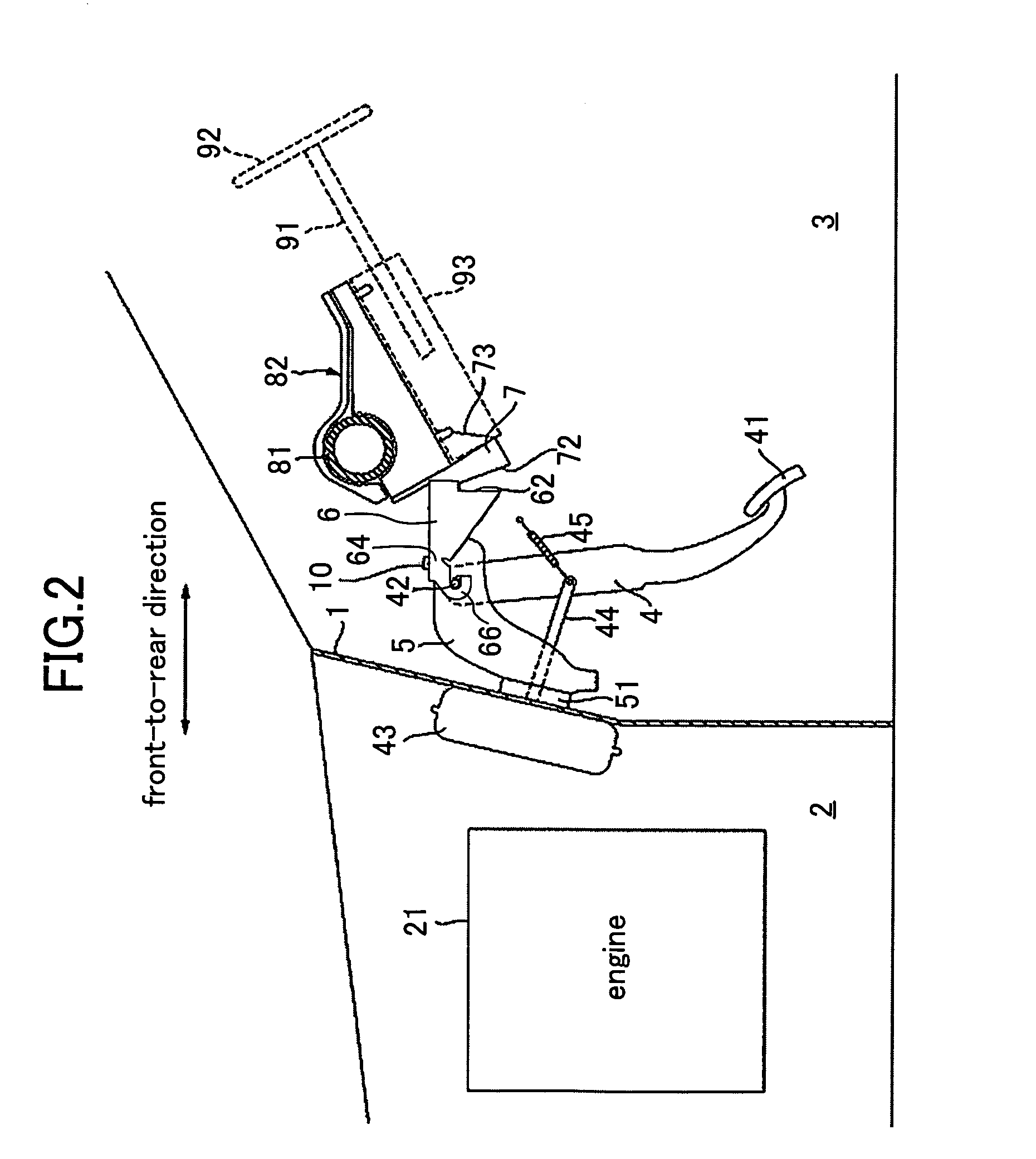
[0077]Next, a pedal assembly support structure according to the present invention will be described with reference to FIGS. 2 to 5.

[0078]The brake pedal lever 4 is placed rearward of the dash panel 1 to extend vertically. The brake pedal lever 4 is provided at its lower end with a pedal 41 operable by a stepping action of a driver's foot, and provided at its upper end with a pivot shaft 42 extending in the vehicle width direction to support the brake pedal lever 4 for angular movement in the vehicle front-to-rear direction. An operating rod 44 is connected to a substantially middle point of the brake pedal lever 4 between the pedal 41 and the pivot shaft 42 to pass through the dash panel 1 from a master back 43 fixed at the rear end of the engine room 2 to the dash panel 1 and extend into the passenger room. A coil spring 45 is connected to the substantially middle poison of the brake pedal lever 4 to bias the brake pedal lever 4 rearward.

[0079]The pedal bracket 5 consists of a subs...

second embodiment

[0116]FIG. 11 is a cross-sectional view corresponding to FIG. 10, showing a variant of the As shown in the figure, the flat surface of each flanged nut 68 comes into surface contact with the associated restriction tab 66 of the guide member 6 through a low-friction member 69 having a lower coefficient of friction than metal. The low-friction member 69 is made, for example, from resin.

[0117]Next, description will be made of the behavior of the pedal assembly support structure of the second embodiment in a vehicle frontal collision.

[0118]When a load larger than the predetermined value acts on the dash panel 1 in a vehicle collision, the dash panel 1 significantly moves backward. The pedal bracket 5 fixed to the dash panel 1 significantly moves backward with the backward movement of the dash panel 1. As a result, the pivot shaft 42 normally engaged with the restriction tabs 66 and 66 (before a vehicle collision) relatively moves backward through the openings formed at the rears of the...

third embodiment

[0130]As described above, in the vehicle pedal assembly support structure of the third embodiment, the sidewalls 53 and 53 of the pedal bracket 5 form overlapped parts 80 and 80 together with the corresponding restriction tabs 66 and 66, respectively, of the guide member 6 and the overlapped parts 80 and 80 have projections 70 and 70 between the sidewalls 53 and 53 and the restriction tabs 66 and 66 of the guide member 6. Therefore, even if the direction of a collision load input from the dash panel 1 to the pedal bracket 5 at the vehicle collision is inclined vertically or laterally to the vehicle front-to-rear direction, for example, because the collision is an offset collision, the relative position of the pedal bracket 5 to the guide member 6 is restricted and thus maintained. This makes it difficult for the pedal bracket 5 to relatively shift in directions other than the vehicle rearward direction to the guide member 6. As a result, even in an offset collision, the pedal bracke...


PUM


Abstract

A vehicle pedal assembly support structure comprises: a bracket to which a pivot shaft for a pedal lever is mounted; a guide member fixed to a vehicle body member other than a dash panel; a fixing mechanism for normally fixing a rear end portion of the bracket to a front end portion of the guide member but disengaging the bracket from the guide member in a vehicle collision; and a relative shift restricting member for restraining the rear end portion of the bracket from relatively shifting in directions other than the rearward direction of the vehicle to the front end portion of the guide member. The guide member is provided with a guide surface for downwardly guiding the bracket moving backward in the vehicle collision to change the posture of the bracket.

Description

CROSS-REFERENCES TO RELATED APPLICATIONS[0001]This application claims priority under 35 USC 119 to Japanese Patent Application No. 2004-279195, filed on Sep. 27, 2004, Japanese Patent Application No. 2004-366228, filed on Dec. 17, 2004, and Japanese Patent Application No. 2004-369335, filed on Dec. 21, 2004, the entire contents of all of which are incorporated herein by reference.BACKGROUND OF THE INVENTION[0002](a) Field of the Invention[0003]This invention relates to a support structure for a pedal assembly for use with a vehicle.[0004](b) Description of the Related Art[0005]In car collisions, as is often the case, a car cannot be fully stopped even though the driver brakes the car by stepping on a brake pedal for the purpose of avoidance of a collision, resulting in the collision, namely, the car leads to the collision with the brake pedal trod.[0006]In such a case, a front car body goes to collapse while absorbing energy of the collision, and an engine placed in an engine room g...

Claims


Application Information

Patent Timeline
Patent Type & Authority Patents(United States)
IPC IPC(8): B60K28/10G05G1/30
CPCB60R21/09B60T7/065Y10T74/20528Y10T74/20888
Inventor HAYASHI, KOUJI
Owner MAZDA MOTOR CORP
Why Eureka
Try Eureka