Projectile trap and shooting range

a projectile trap and shooting range technology, applied in the field of shooting ranges, can solve the problems of negative air pressure system energy consumption, contamination, unsatisfactory results,

Active Publication Date: 2008-10-14
WACHOVIA BANK N A ADMINISTRATIVE AGENT
View PDF16 Cites 15 Cited by
  • Summary
  • Abstract
  • Description
  • Claims
  • Application Information

AI Technical Summary

Benefits of technology

[0007]This disclosure is directed to a shooting range including a shooting station and a projectile trap. In an embodiment, the shooting range includes one

Problems solved by technology

One such prior art dry system apparatus produces a negative air pressure within the trap, but this has proven unsatisfactory because the negative air pressure may unnecessarily pull lead from the trap that would otherwise be removed by a collection system at the bottom of the trap.
Thus, this kin

Method used


Image

  • Projectile trap and shooting range
  • Projectile trap and shooting range
  • Projectile trap and shooting range

Examples


Embodiment Construction

[0019]In the following description, like reference characters designate like or corresponding parts throughout the several views. Also in the following description, terms such as “forward,”“left,” and “downwardly,” are words of convenience and are not limiting terms. The illustrations provided are for describing embodiments of a shooting range and do not limit the range to any particular embodiment shown or described.

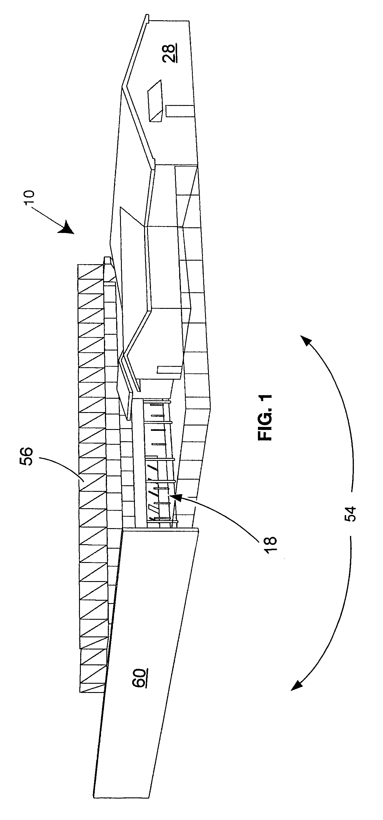
[0020]FIG. 1 shows an embodiment of a shooting range, generally designated 10, constructed according to the present inventions. The shooting range 10 includes a safety area 28 where firearms may be inspected and readied. In addition, range management may have offices adjacent or in the safety area 28. Limited access to the shooting range 10 may be provided by additional fencing and supplemented, in part, by a containment system, generally designated 54.

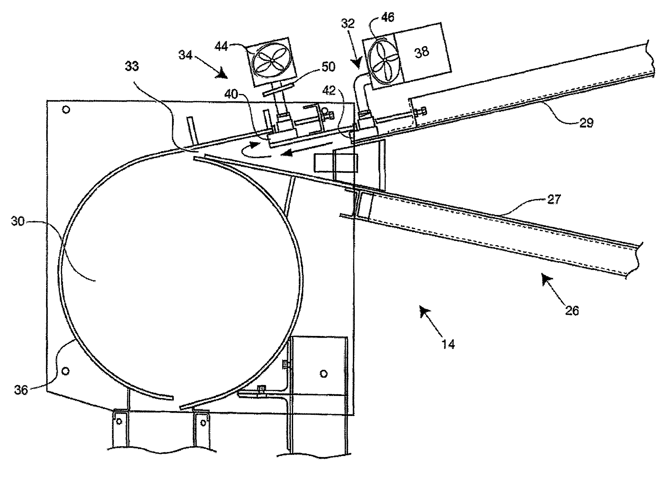
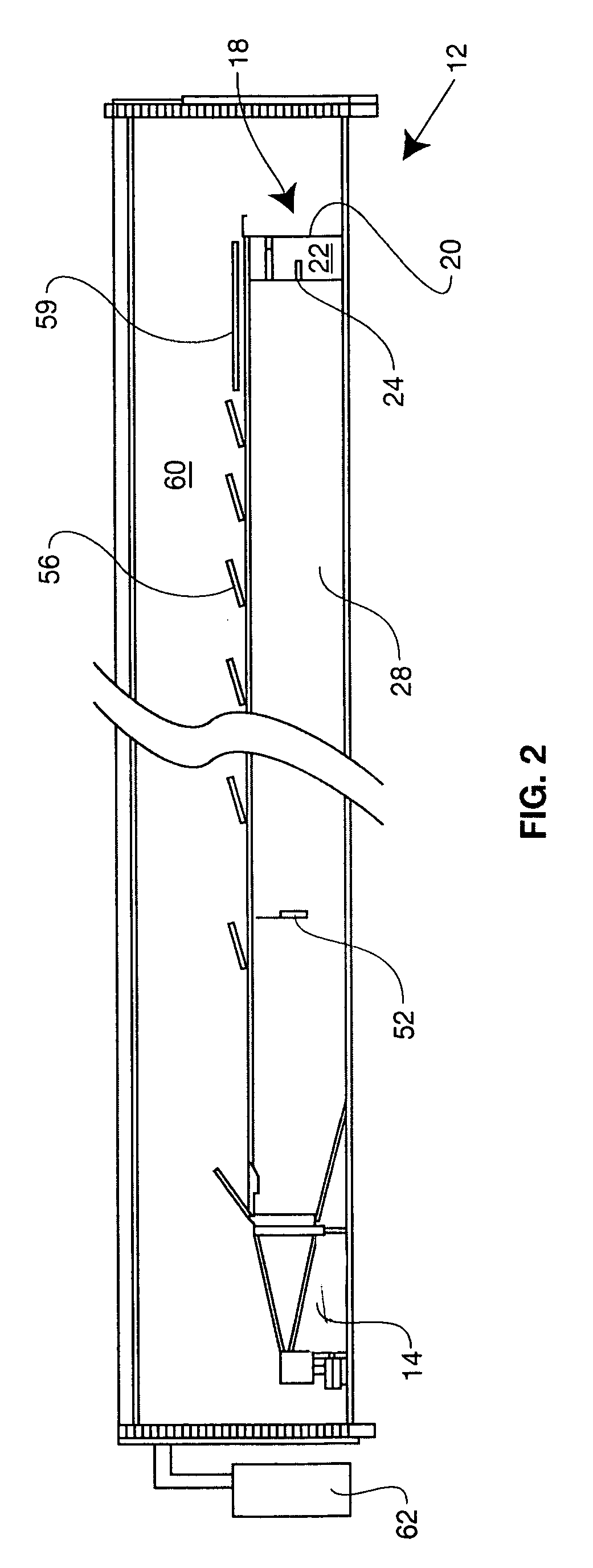
[0021]FIG. 2 is a cross-sectional view of a portion of shooting range 10. FIG. 2 shows a shooting station 12, a project...


PUM


Abstract

A shooting range that may include one or more of a shooting station, a projectile trap and or at least one range auxiliary. In one embodiment of the inventions, the projectile trap includes a trap chamber, an air injection system and an air collection system.

Description

BACKGROUND[0001](1) Field of the Disclosure[0002]This disclosure relates to shooting ranges of the kind including a projectile trap and a projectile trap for varied uses, including for use in a shooting range.[0003](2) Description of Prior Art[0004]The design and operation of shooting ranges is a sophisticated engineering matter in which safety is paramount. Thorough discussions of the design and layout of modern shooting ranges may be found in “Design Criteria for Shooting Ranges” by C. Vargas, Third National Shooting Range Symposium (1996); Army Regulation AR 385-63 “Range Safety”; Navy Handbook (MIL-HDBK) 1027 / 3B, “Range Facilities and Miscellaneous Training Facilities Other Than Buildings” and the National Rifle Association's “NRA Range Source Book.” These references are hereby incorporated by reference in their entirety.[0005]Shooting ranges having projectile traps are known. Heretofore, the traps have included various apparatuses for preventing fragments of lead and other meta...

Claims


Application Information

Patent Timeline
IPC IPC(8): F41J1/12F41J1/18F41J11/00F41J13/00
CPCF41J11/00F41J13/00
Inventor COBURN, RONALDNESTER, CHARLES EDWARDKILLOY, CHRISTOPHER JOHN
Owner WACHOVIA BANK N A ADMINISTRATIVE AGENT
Why Eureka
Try Eureka