Performance state management

a technology of performance state and management, applied in the direction of instruments, nuclear elements, heat measurement, etc., can solve the problems of wasting energy, wasting energy, and wasting resources,

Active Publication Date: 2008-10-14
TAHOE RES LTD
View PDF11 Cites 197 Cited by
  • Summary
  • Abstract
  • Description
  • Claims
  • Application Information

AI Technical Summary

Problems solved by technology

Since high utilization often means using a high operational frequency and concomitant high power, this approach often results in losing opportunities to save energy.
For example, when a memory-dependent task is performed, with generally high utilization, the processor can stall at some point waiting for data.
Running the processor at a high frequency during the stall period can result in needless energy use.

Method used


Image

  • Performance state management
  • Performance state management
  • Performance state management

Examples


Embodiment Construction

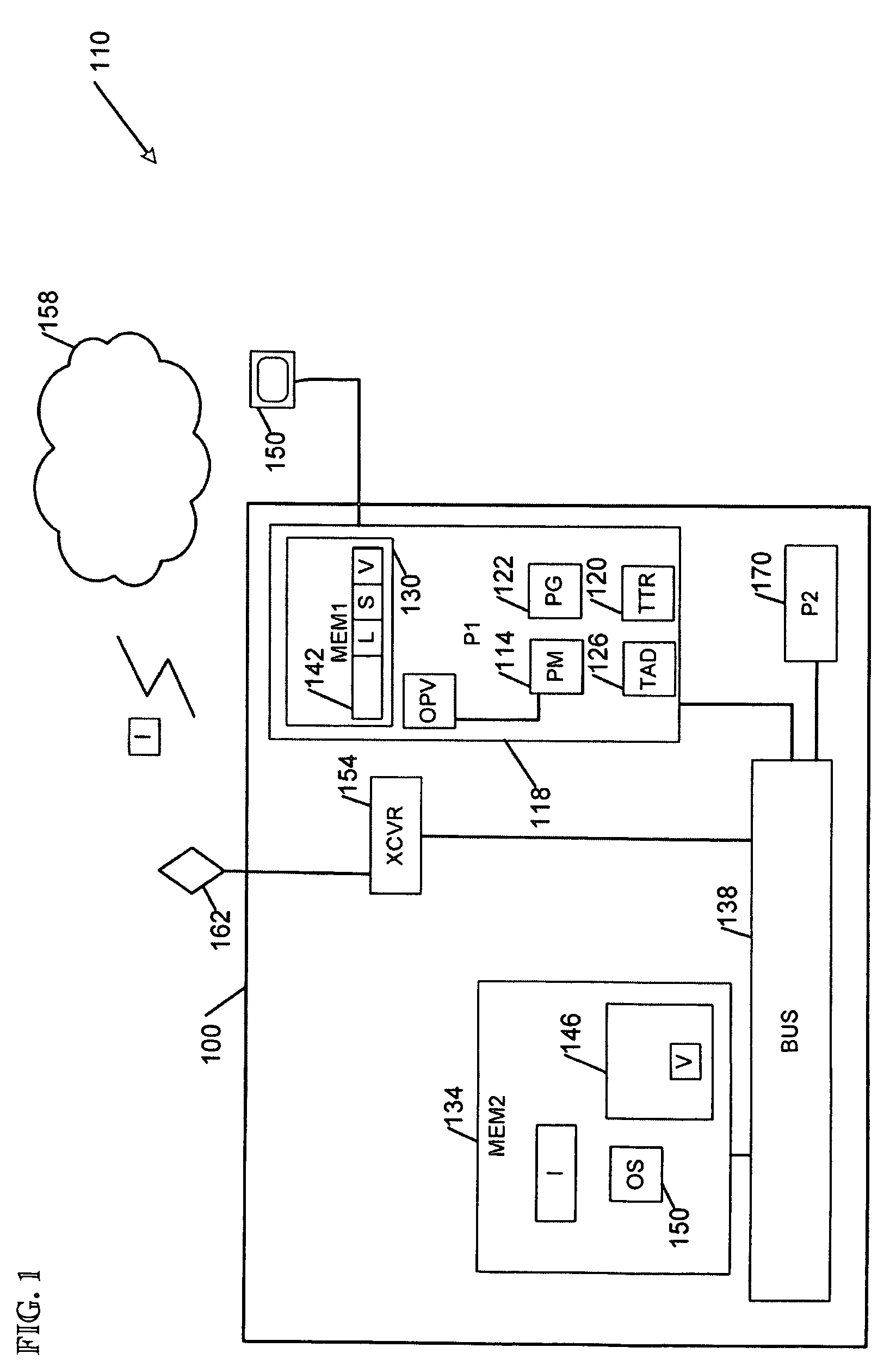
[0006]FIG. 1 is a block diagram of apparatus 100 and systems 110 for performance state management according to various embodiments of the invention. In some embodiments, the performance state management apparatus 100 may include output measurement logic 114 to measure an output performance metric value OPV associated with a processor 118 (and perhaps a P state linked to the current processor operation frequency). The apparatus 100 may also include performance governor logic 122 to set a determined, or new operation frequency of the processor 118 responsive to the output performance metric value OPV.

[0007]Thus, the apparatus 100 may operate in conjunction with a defined performance metric based upon processor / computer system output, such that P states can be managed based on the value of the metric. The end result is that energy can be saved because the lowest possible operating frequency (that has little or no perceivable impact on performance) may be used to operate the processor / c...


PUM


Abstract

Some embodiments of the invention may operate to measure a first output performance metric value associated with a current operation frequency of a processor, to set a trial operation frequency of the processor, and to measure a second output performance metric value associated with the trial operation frequency. If the measured performance variation is less than a specified acceptable performance variation, the trial operation frequency may be selected as a subsequent determined operation frequency.

Description

TECHNICAL FIELD [0001]The various embodiments described herein relate to managing processor performance generally, including apparatus, systems, and methods used to manage processor power usage.BACKGROUND INFORMATION [0002]Current methods of managing processor performance states (sometimes known as P states) are usually based on processor utilization. Since high utilization often means using a high operational frequency and concomitant high power, this approach often results in losing opportunities to save energy. For example, when a memory-dependent task is performed, with generally high utilization, the processor can stall at some point waiting for data. Running the processor at a high frequency during the stall period can result in needless energy use.BRIEF DESCRIPTION OF THE DRAWINGS [0003]FIG. 1 is a block diagram of apparatus and systems for performance state management according to various embodiments of the invention.[0004]FIG. 2 is a flow diagram illustrating several method...

Claims


Application Information

Patent Timeline
Patent Type & Authority Patents(United States)
IPC IPC(8): G06F11/30
CPCG06F1/3203G06F1/324Y02B60/1217Y02D10/00
Inventor SONG, JUSTINBODAS, DEVADATTA
Owner TAHOE RES LTD
Why Eureka
Try Eureka