Eureka AIR delivers breakthrough ideas for toughest innovation challenges, trusted by R&D personnel around the world.

Load sensing safety device for vertical lift

a safety device and vertical lift technology, applied in the field of lifts, can solve the problems of patient injury, increased risk of injury, and increased risk of patient injury

Active Publication Date: 2008-10-21
JOERNS HEALTHCARE
View PDF35 Cites 19 Cited by
  • Summary
  • Abstract
  • Description
  • Claims
  • Application Information

AI Technical Summary

Benefits of technology

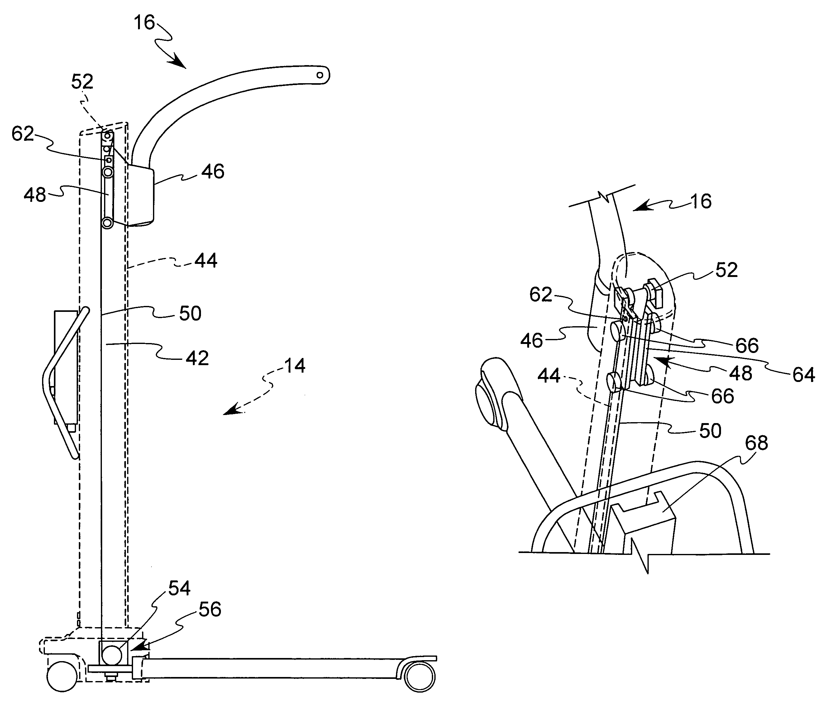
[0005]The present invention is directed towards a lift for lifting and transporting patients, and a load sensing safety device for the lift. The load sensing safety device comprises a pulley shaft carrying a pulley, which, in turn, carries a belt that effectuates movement of the patient lift boom. A...

Problems solved by technology

The boom and patient support rigging are often very heavy.
If the patient should come into contact with an underlying obstruction and the actuator continues to lower the boom, the weight of these components can be applied against the patient, resulting in patient injury.
When the lift employs a flexible belt to transmit lifting force, further potential for injury exists if a patient encounters an underlying obstruction because the belt may continue to be extended and accumulate as slack.

Method used


Image

  • Load sensing safety device for vertical lift
  • Load sensing safety device for vertical lift
  • Load sensing safety device for vertical lift

Examples


Embodiment Construction

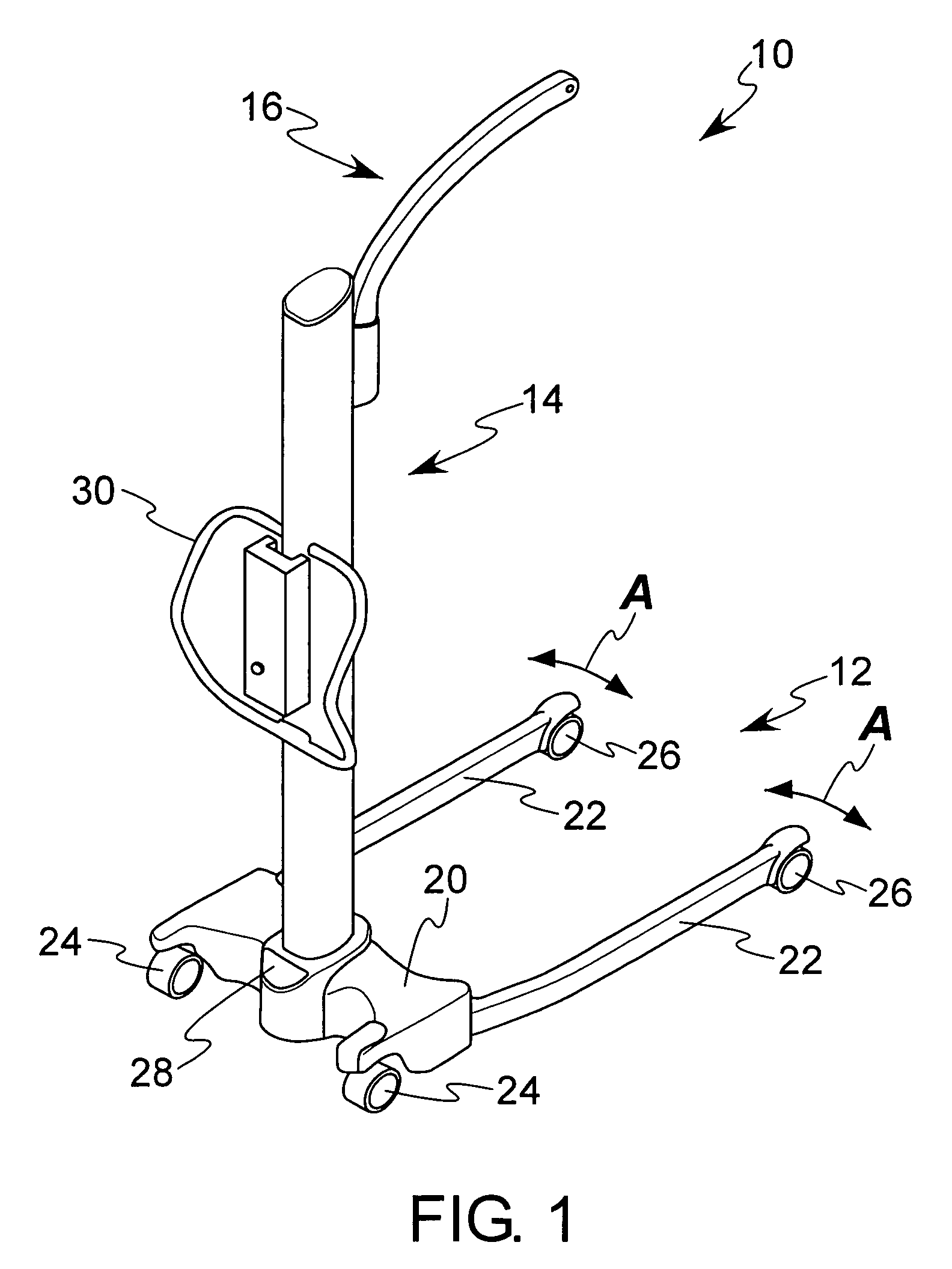
[0012]Referring now to the drawings, there is illustrated in FIG. 1 a lift 10 for lifting and transporting patients. The lift 10 generally comprises a base 12 supported for movement relative to a supporting surface, a mast 14 extending vertically upward from the base 12, and a boom 16 supported for movement relative to the mast 14. Although not shown, a forward extending free end of the boom 16 is subject to support rigging, such as a cradle or sling hanger, which are well known in the art of the invention.

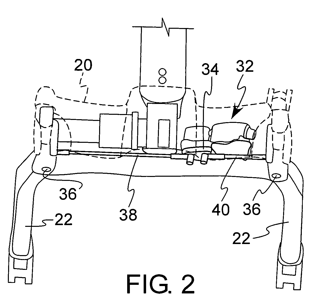
[0013]The base 12 generally includes a housing 20 and legs 22 extending forwardly from the housing 20. The rear end of the base 12 and the forward ends of the legs 22 are supported relative to a supporting surface by rear and front wheels or casters 24, 26. The casters, preferably the rear casters 24, are preferably provided with a brake that may be effectuated by a lever (not shown) to prevent the casters 24 from rotating and thus prevent the lift 10 from moving relative to the s...


PUM


Abstract

A load sensing safety device comprises a pulley shaft carrying a pulley. The pulley, in turn, carries a belt that effectuates movement of the patient lift boom. A biasing element applies a spring force against the pulley shaft to move the pulley shaft in a first direction. A switch that opens and closes responsive to movement of the pulley shaft, whereby the switch opens where the pulley shaft is moved to a first position by movement of the spring in the first direction.

Description

BACKGROUND OF INVENTION[0001]This invention relates in general to lifts for lifting and transporting patients. More particularly, the invention relates to a load sensing safety device for patient lifts and more particularly for vertical lifts.[0002]Lifts for lifting and transporting patients are well known. Such lifts typically include a base that is usually supported for movement relative to a supporting surface, such as a floor. Extending upwardly from the base is a mast and extending forward from the mast is a boom. From a forward end of the boom is suspended a rigging of some sort, such as a sling hanger for supporting a sling, which in turn is provided for supporting the patient. The boom is displaceable to vertically move the rigging to raise and lower a patient supported by the rigging. With the patient supported by the rigging, the lift may merely support the patient in a fixed position, or the lift may be moved relative to the supporting surface to transport the patient.[00...

Claims


Application Information

Patent Timeline
IPC IPC(8): A61G7/10B66D1/06B66F17/00
CPCA61G7/1019A61G7/1046A61G7/1067B66D1/06B66F17/00
Inventor BURNS, RALPH E.
Owner JOERNS HEALTHCARE
Why Eureka
Eureka Blog
Learn More