Shift mechanism for trim mower cutting units

a technology of shifting mechanism and trim mower, which is applied in the field of trim mowers, can solve the problems of reducing the productivity of the trim mower in flatter areas, the cutting width the uncut grass of the trim mower, so as to increase the overlap, reduce the cutting width, and reduce the effect of productivity

Active Publication Date: 2008-10-21
DEERE & CO
View PDF17 Cites 8 Cited by
  • Summary
  • Abstract
  • Description
  • Claims
  • Application Information

AI Technical Summary

Benefits of technology

[0010]A shift mechanism is provided for trim mower cutting units, that allows each cutting unit to mow grass in small or enclosed areas of golf courses, especially around the edges of hazards such as sand traps and bunkers, but that will not sacrifice productivity when mowing other areas. The shift mechanism is capable of increasing the mower's cutting width, or increasing the overlap between front and rear cutting units. The shift mechanism also helps reduce the loss of vehicle stability when mowing on side hills or hazards while a cutting unit is moved laterally. The shift mechanism can reduce the risk of damage to the edges of sand traps and bunkers.

Problems solved by technology

These areas may require a trim mower having a relatively narrow cut width because the areas may include undulating terrain, or may be too small or confined for larger mowing machines.
Crabbing may cause the trim mower to leave uncut strips of grass.
However, greater overlap also can reduce a trim mower's cutting width, resulting in lower productivity of the trim mower in flatter areas.
When trim mowers are used to cut grass at or near the edge of a golf course hazard such as a sand trap or bunker, or other golf course feature, the machine's weight may cause the bunker wall to collapse, especially in sandy soil conditions.
Additionally, a trim mower weighing 1000 pounds or more may slide into a sand trap or bunker, get stuck, become high centered, or experience reduced stability.
When trimming around an obstacle on a slope with the cutting units shifted to the downhill side, the trim mower may experience reduced stability because all cutting units are shifted by a single carrier which supports its own weight along with weight of the cylinders and lift arms.
When this weight and the cutting units are shifted to the downhill side, the center of gravity of the machine is moved into a less favorable position that can lead to reduced stability.
If both cutting units are shifted to one side of the machine with the single carrier frame, the opposite side tire may roll on uncut turf, resulting in poor cut quality and an unsightly cut pattern.
These devices are not well suited and have not been adapted for use on trim mowers that are used to cut rough and fringe areas on a golf course.

Method used


Image

  • Shift mechanism for trim mower cutting units
  • Shift mechanism for trim mower cutting units
  • Shift mechanism for trim mower cutting units

Examples


Embodiment Construction

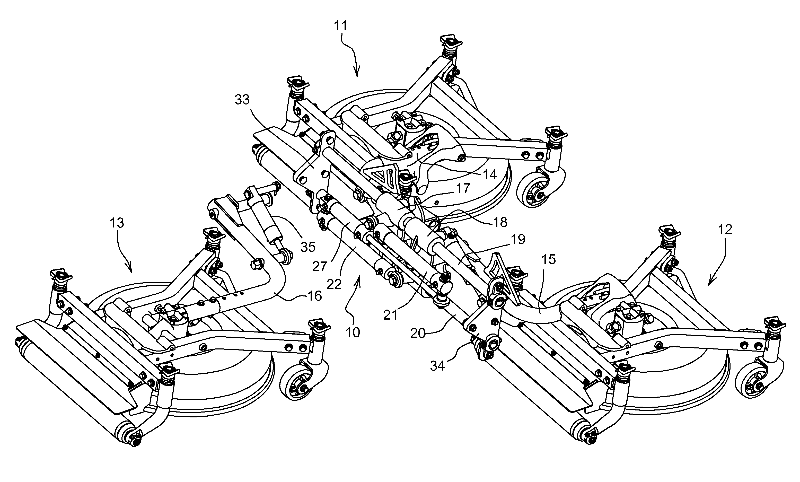
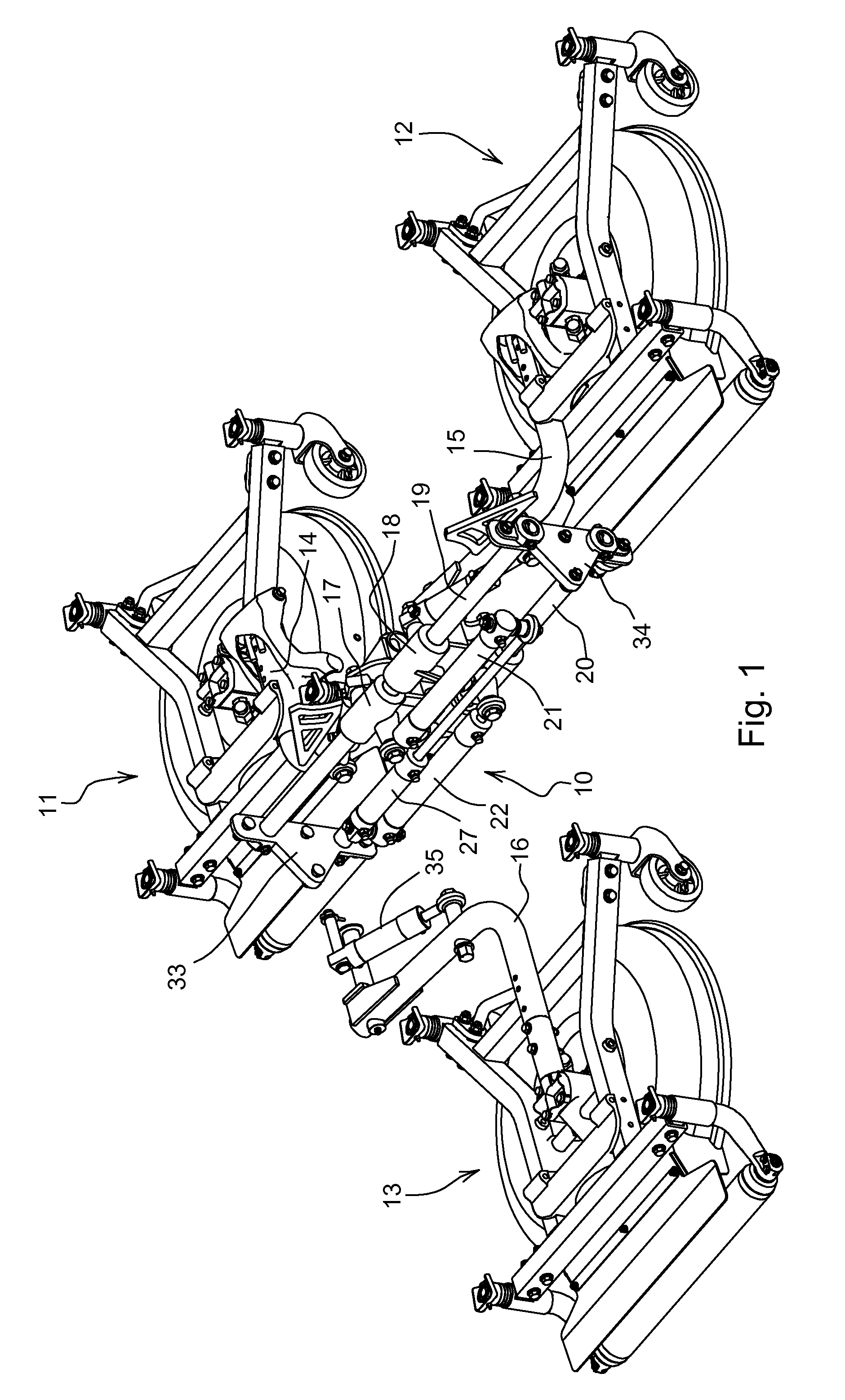
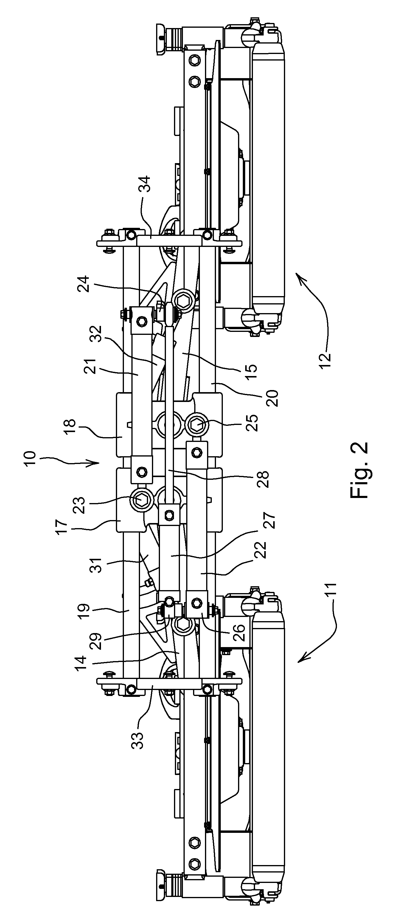
[0016]As shown in FIGS. 1-3, in one embodiment of the invention, shift mechanism 10 may be provided on a self-propelled trim mower having three separate cutting units 11, 12, 13. For example, the self propelled trim mower may include a frame supported by left and right front drive wheels, a steerable rear wheel, an engine compartment arranged on a frame over and / or slightly forward of the rear wheel. The shift mechanism of the present invention, however, may be employed on various types and configurations of mowing vehicles other than trim mowers.

[0017]In one embodiment, cutting units 11, 12, 13 may be hydraulically or electrically powered. For example, as shown in FIGS. 1-3, each cutting unit may be a mower deck covering a rotary cutting blade. Alternatively, each cutting unit may be a reel-type cutting unit with a horizontally aligned reel that cuts the grass between a spiral blade and bedknife.

[0018]In one embodiment, shift mechanism 10 is used for two front cutting units 11, 12 ...


PUM


Abstract

A shift mechanism for trim mower cutting units includes a pair of slidable carriers. Each slidable carrier can slide along a pair of guide rods mounted to a mower frame. A hydraulic extension cylinder is connected to each slidable carrier and independently extends to move the slidable carrier laterally outward from the mower frame or retracts to move the slidable carrier laterally inward in relation to the mower frame. A hydraulic shifting cylinder is mounted between the two extension cylinders and extends to shift both slidable carriers laterally inward toward a center position, and retracts to move both slidable carriers laterally outward toward an extended position.

Description

FIELD OF THE INVENTION[0001]This invention relates generally to grass mowing machines, and particularly to trim mowers used to cut grass on small or enclosed rough and fringe areas, and around bunkers and sand traps of golf courses.BACKGROUND OF THE INVENTION[0002]Trim mowers, also sometimes referred to as utility mowers, may be used to mow the smaller and / or enclosed rough and fringe areas on golf courses. These areas may require a trim mower having a relatively narrow cut width because the areas may include undulating terrain, or may be too small or confined for larger mowing machines. Trim mowers may include three cutting units powered by and attached to a traction vehicle. For example, two front cutting units may be positioned forward of the vehicle's front pair of wheels, and a rear cutting unit may be between the front wheels and a single rear wheel used for steering. The rear cutting unit may cut a swath between the two front cutting units that overlaps the swaths cut by the ...

Claims


Application Information

Patent Timeline
Patent Type & Authority Patents(United States)
IPC IPC(8): A01D34/00
CPCA01D34/863A01D75/306A01D34/661
Inventor LINK, TODD ALLENWITWER, JEFFREY DAVIDHONEYCUTT, JASON MCLAMBPEARMAN, BRIAN KEITHREICHEN, RONALD LEE
Owner DEERE & CO
Why Eureka
Try Eureka