A double-arc turning blade

A double arc and blade technology, applied in cutting blades, tools for lathes, turning equipment, etc., can solve the problems of affecting the service life of tools, reducing processing efficiency, easy to generate vibration, etc., so as to improve processing efficiency and increase cutting tools. Durability, the effect of increasing the cutting width

Active Publication Date: 2018-11-23
HARBIN UNIV OF SCI & TECH
View PDF9 Cites 0 Cited by
  • Summary
  • Abstract
  • Description
  • Claims
  • Application Information

AI Technical Summary

Problems solved by technology

The arc-shaped wiper blade, the larger the radius of curvature, the higher the finish of the machined surface and the durability of the tool, but it will also increase the grinding force, easily generate vibration, and reduce the processing efficiency. Long-term use of the tool is easy to damage, which affects the use of the tool life

Method used


Image

  • A double-arc turning blade
  • A double-arc turning blade
  • A double-arc turning blade

Examples


specific Embodiment approach 1

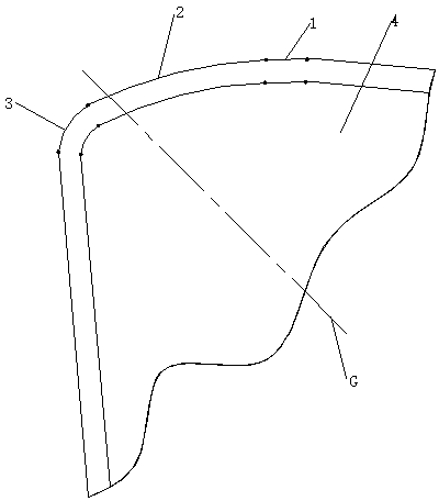
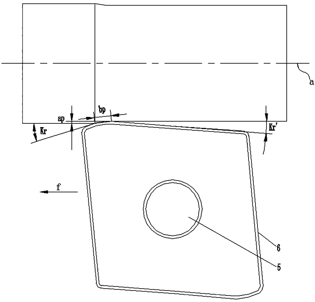
[0018] Specific implementation mode one: as figure 1 and figure 2 As shown, a double-arc turning blade is composed of a cutter body 6 and a knife tip insert 4. The middle part of the cutter body 6 is provided with a tool holder mounting hole 5, and the horizontal section of the cutter body 6 is The shape is polygonal, and any corner of the upper surface VI of the cutter body 6 is provided with an embedding groove that matches the blade tip insert 4, and the blade tip insert 4 is tightly embedded in the embedding groove of the cutter body 6, so The side of the turning insert includes a side I, a side two V and a cutting corner M, the side I and the side two V are located on both sides of the cutting corner M, and the cutting edge insert 4 has a cutting edge A cutting section, the cutting section of the knife edge is processed with a negative chamfer VIII;

[0019] The cutting corner M includes a curved surface II, a curved surface III, a smoothing surface IV and three cuttin...

specific Embodiment approach 2

[0022] Specific implementation mode two: as figure 1 and figure 2 As shown, for the double-arc cutting insert described in Embodiment 1, the point where the arc cutting edge 1 2 and the arc cutting edge 2 3 intersect is the highest point, and the arc cutting edge 2 3 intersects with the center line G of the cutting corner M, and the arc cutting edge 2 3 is asymmetrically arranged on the center line of the cutting corner M, and the highest point is set near the center line of the cutting corner M (two arcs The point on the cutting edge cannot exceed the highest point).

specific Embodiment approach 3

[0023] Specific implementation mode three: as figure 1 As shown, for the double-arc turning blade described in Embodiment 1, the width of the negative chamfer VIII is in the range of 0.15-0.24mm, and the range of the angle of the negative chamfer VIII is -5°~-25° °. The effect is: If the chamfer width and chamfer angle are too large, the cutting force generated during the cutting process will be too large, and the vibration generated during machining will also increase, which will affect the quality of the processed surface. If the value is too small, the effect of chamfering is not obvious.


PUM


Abstract

The invention provides a double-circular-arc turning tool blade and belongs to the technical field of turning tools. The invention aims at providing the double-circular-arc turning tool blade which can improve the machining efficiency and the surface finish degree and can prolong the service life. An embedding groove matched with a tool nose embedding sheet is arranged at any one vertex angle of an upper surface of a tool body; the tool nose embedding sheet is tightly embedded into an embedding groove of the tool body; a side face I and a side face II are of the turning tool blade are located at two sides of a cutting corner part; the tool nose embedding sheet is provided with a tool nose cutting section and a negative chamfered edge is machined on the tool nose cutting section; the cutting corner part comprises a curved surface I, a curved surface II, a smoothening surface and three cutting edges; the three cutting edges are arranged at a lower edge of the negative chamfered edge of the tool nose embedding sheet; the three cutting edges comprises a linear cutting edge, a circular-arc cutting edge I and a circular-arc cutting edge II respectively; the side face I is tangent to the curved surface I and the curved surface I is tangent to the curved surface II; the curved surface II and the smoothening surface are connected through a smooth transition surface and an included angle is formed between the smoothening surface and the side face II. The double-circular-arc turning tool blade is applicable to finish turning machining.

Description

technical field [0001] The invention relates to a turning insert, which belongs to the technical field of turning tools. Background technique [0002] The wiper blade can repair the residual metal left on the machined surface during the tool pass, reducing the surface roughness. The wiper blade must be ground straight and clean. When installing, it should be kept parallel to the feed direction. The wiper edge should not be too large, as it will increase the radial resistance of cutting and easily cause vibration. And only when the rigidity of the process system such as the workpiece, tool, fixture and machine tool is good, the use of the wiper can achieve better results. The length of the wiper blade is generally 1.2 to 1.5 times the feed rate. The wiper blade adopts a feed rate twice that of the standard blade, and the same surface finish can still be obtained. The advantage of the wiper edge is "halving the machining time and doubling the surface quality". [0003] The...

Claims


Application Information

Patent Timeline
Patent Type & Authority Patents(China)
IPC IPC(8): B23B27/00
CPCB23B27/00B23B2200/08B23B2200/28
Inventor 陈涛王道源刘献礼李素燕
Owner HARBIN UNIV OF SCI & TECH
Why Eureka
Try Eureka