Groove milling method and high-speed milling cutter device

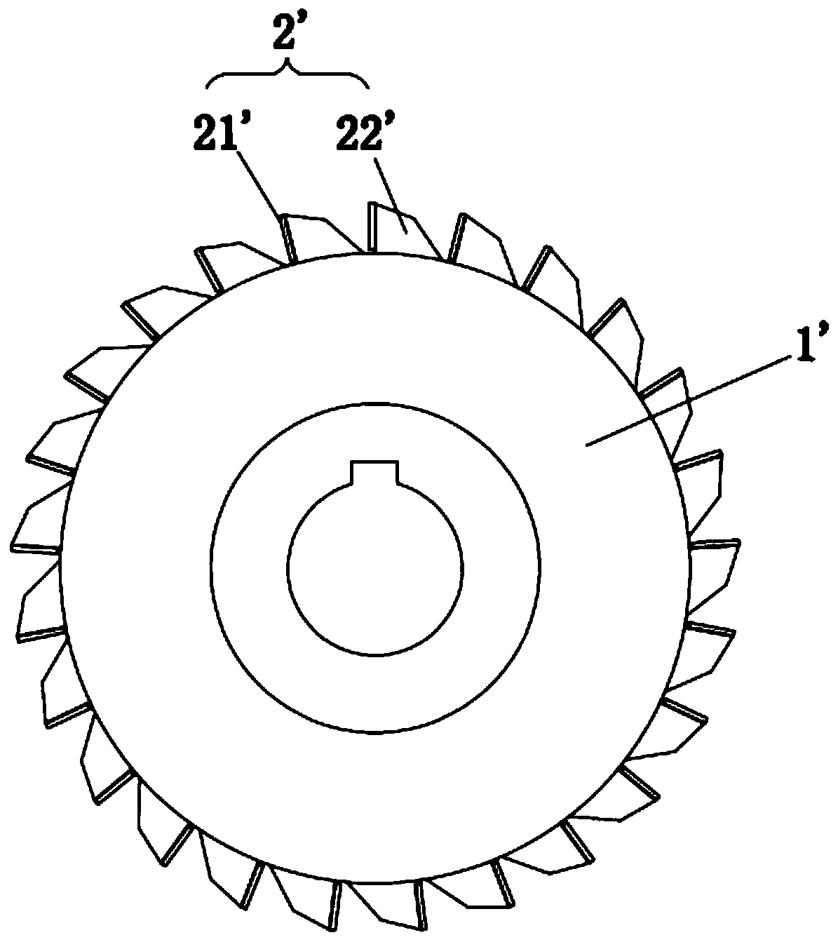
A cutter device, high-speed milling technology, applied in milling cutters, positioning devices, milling machine equipment, etc., can solve the problems of shortening the service life of the cutter teeth 2', hindering the cutting action, and deteriorating the milling efficiency, so as to reduce costs and maintenance. Difficulty, avoid rotation instability, ensure the effect of strength and rigidity

Pending Publication Date: 2019-09-10
颜亚秀
View PDF0 Cites 0 Cited by
  • Summary
  • Abstract
  • Description
  • Claims
  • Application Information

AI Technical Summary

Problems solved by technology

Although this structure has a large number of cutter teeth 2', there is a problem that the larger the number of cutter teeth 2', the narrower the space between two adjacent cutter teeth 2', and the cutter teeth 2' are cutting After the workpiece, the chip is not easy to discharge from the rear side of the tooth 2'
If the chip is not discharged in time, it will hinder the cutting action of the rear tooth 2', resulting in poor milling efficiency
Although more chip removal space can be obtained by increasing the inclination angle of the rear side of the cutter tooth 2', the increase of the rear side inclination angle of the cutter tooth 2' will reduce the support force of the cutter tooth body 22' to the blade 21', resulting in a single cutter The cutting ability of tooth 2' becomes worse
Moreover, the cutting ranges of the front and rear cutter teeth 2' on the current milling cutter overlap, and the cutting width of the milling cutter per revolution is relatively limited, and increasing the width of a single cutter tooth 2' will also increase the resistance of each cutting, not only Requires a more powerful drive mechanism and also shortens the service life of the teeth 2'
Therefore, when the current three-sided edge milling cutter is milling grooves for large equipment, its feed rate is about 30mm / min, and the speed is 300-400r / min, and its milling efficiency is very slow.
[0004] In addition, the problem caused by the large number of cutter teeth is that the price of the entire milling cutter is high, and maintenance is difficult and takes a long time

Method used


Image

  • Groove milling method and high-speed milling cutter device
  • Groove milling method and high-speed milling cutter device
  • Groove milling method and high-speed milling cutter device

Examples


Embodiment

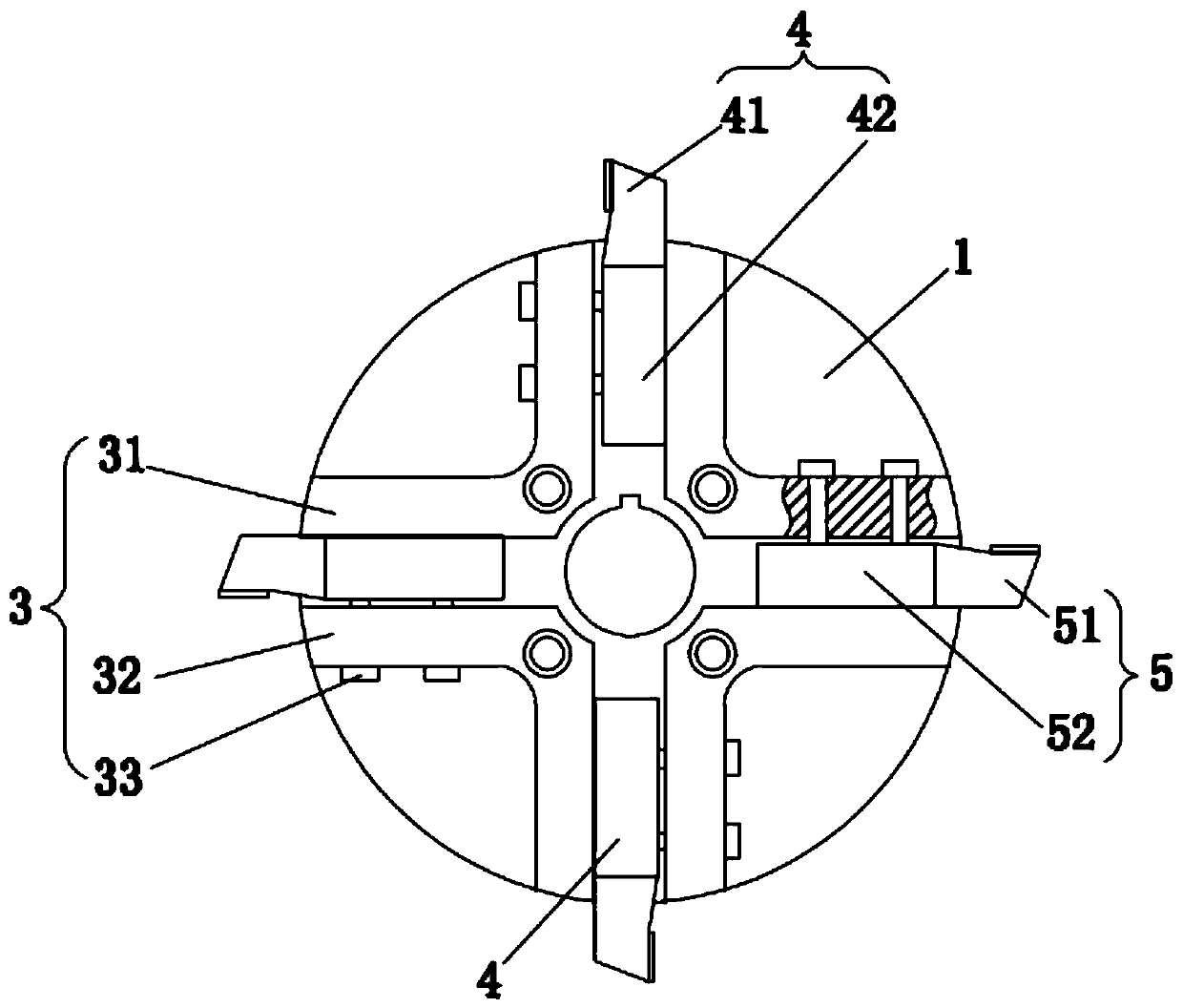
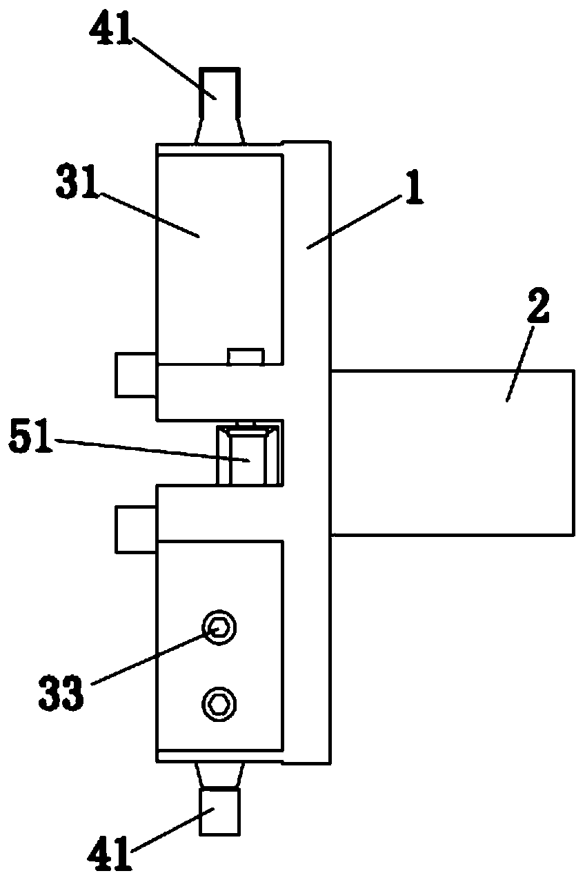
[0029] The specific embodiment of the present invention is as Figure 2 to Figure 4 As shown, a high-speed milling cutter device includes a turntable 1, and two cutter sets are arranged on the turntable 1, and two cutters are arranged around the rotation axis of the turntable 1 in each cutter set, that is, four cutter sets are arranged on the turntable 1 , the four cutters are evenly distributed around the axis of rotation of the turntable 1. One side of the turntable 1 is provided with an installation shaft 2 for connecting with the power mechanism, and the installation shaft 2 is coaxially arranged with the turntable 1 . In a tool group, the cutting range of two adjacent tools is staggered along the milling groove width direction and partially overlapped, that is, among the two adjacent tools in a tool group, the cutting edge of one side of the front tool protrudes from the rear tool The same side cutting edge of the front cutter is located between the two side cutting edge...


PUM


Abstract

The invention discloses a groove milling method and a high-speed milling cutter device. The groove milling method comprises the steps that at least two cutters in a cutter set on a milling cutter turntable rotate along with the turntable, and the workpieces are sequentially cut; and in the same cutter set, the cutting ranges of every two adjacent cutters in front and back are staggered in the width direction of the groove milling and partially overlapped. The high-speed milling cutter device comprises the turntable, at least one cutter set is arranged on the turntable, and one cutter set comprises at least two cutters arranged around a rotation axis of the turntable; in every two adjacent cutters in the cutter set, a cutting edge on one side of the front cutter protrudes out of the cuttingedge on the same side of the a back cutter; the cutting edge of the other side of the front cutter is positioned between the cutting edges on the two sides of the back cutter; and the cutting edge onthe other side of the back cutter protrudes out of the cutting edge at the same side of the front cutter. According to the groove milling method and the high-speed milling cutter device, the cuttingwidth of one-circle rotation of the milling cutter is large, the service life of the cutter can be ensured to be long enough, and the groove milling efficiency is high.

Description

technical field [0001] The invention relates to the field of milling cutters, in particular to a groove milling method and a high-speed milling cutter device. Background technique [0002] A milling cutter is a rotating tool with one or more teeth for milling operations. When working, each knife tooth cuts off the allowance of the workpiece intermittently in turn. As a type of milling cutter, the three-side milling cutter can perform groove milling. Among them, three side edge milling cutters are also used for milling grooves of large equipment. [0003] However, when milling slots for large-scale equipment at present, the three-sided edge milling cutter used is as shown in the attached manual. figure 1 Shown, be provided with about 15-30 knife teeth 2 ' on the edge of rotating disk 1 '. When milling slots, the chips are discharged from the rear side of the tooth 2'. Although this structure has a large number of cutter teeth 2', there is a problem that the larger the nu...

Claims


Application Information

Patent Timeline
Patent Type & Authority Applications(China)
IPC IPC(8): B23C3/28B23C5/08B23Q3/12
CPCB23C3/28B23C5/08B23Q3/12
Inventor 颜亚秀林艺明
Owner 颜亚秀
Why Eureka
Try Eureka