Cold plate type heat dissipation system and liquid cooling source

A heat dissipation system and liquid cooling source technology, applied in the direction of cooling/ventilation/heating transformation, electrical components, electrical equipment structural parts, etc., can solve the problem that the condenser cannot perform well on the condensation effect, affects the condensation effect of the condenser, and increases the condensation In order to achieve the effect of facilitating circulation, ensuring heat dissipation performance and speeding up evaporation

Inactive Publication Date: 2019-09-06
CHINA AVIATION OPTICAL-ELECTRICAL TECH CO LTD
View PDF5 Cites 1 Cited by
  • Summary
  • Abstract
  • Description
  • Claims
  • Application Information

AI Technical Summary

Problems solved by technology

[0004] The purpose of the present invention is to provide a liquid cooling source to solve the problem that the cold plate heat dissipation system in the prior art is not equipped with a gas-liquid separator, which causes the heat exchange medium entering the condenser to be in a gas-liquid two-phase mixed state, thereby increasing condensation. The load of the condenser affects the condensation effect of the condenser; the purpose of the present invention is also to provide a cold plate heat dissipation system equipped with the above-mentioned liquid cooling source, so as to solve the problem that the condenser in the system cannot perform the condensation effect well, which leads to poor heat dissipation effect technical problem

Method used


Image

  • Cold plate type heat dissipation system and liquid cooling source

Examples


Embodiment Construction

[0039] Embodiments of the present invention will be further described below in conjunction with the accompanying drawings.

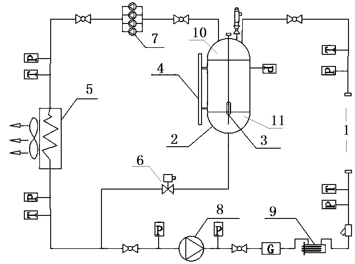
[0040] The specific embodiment of the cold plate type cooling system provided by the present invention, such as figure 1 As shown, including the cold plate and the liquid cooling source connected to the cold plate, the cold plate is made of high thermal conductivity metal alloy materials such as copper, aluminum, etc., the heat exchange medium is installed in the cold plate, and the cooling system is near the cold plate A heating device 1 is provided. The liquid cooling source includes a condenser 5. The condenser 5 has a gas pipeline and a liquid return pipeline for connecting with the cold plate to form a heat exchange medium circulation circuit. The gas pipeline has a gas pipeline for connecting with the gas outlet of the cold plate. The liquid return line has a liquid line interface for connecting with the liquid inlet of the cold plate. The liquid...


PUM


Abstract

The invention relates to a cold plate type heat dissipation system and a liquid cooling source. The cold plate type heat dissipation system comprises a cold plate and the liquid cooling source connected with the cold plate. A heat exchange medium is arranged in the cold plate. The heat dissipation system is provided with a heat generating device at the position close to the cold plate. The liquidcooling source comprises a condenser. The condenser is provided with a gas pipeline and a liquid return pipeline which are used for connecting with the cold plate to form a heat exchange medium circulation circuit. The gas pipeline is provided with a gas path interface for connecting with the gas outlet of the cold plate. The liquid return pipeline is provided with a liquid path interface for connecting with the liquid inlet of the cold plate. A gas-liquid separator is connected in sires on the gas pipeline. The gas storage chamber of the gas-liquid separator is communicated with the gas pipeline. The liquid storage chamber of the gas-liquid separator is connected with the liquid return pipeline through a liquid outlet pipeline. According to the cold plate type heat dissipation system, thecondensation effect of the condenser can be ensured without increasing the load of the condenser so as to have good heat dissipation effect.

Description

technical field [0001] The invention relates to a cold plate heat dissipation system and a liquid cooling source. Background technique [0002] Electronic devices working outdoors and in other harsh environments have high requirements for waterproof, moisture-proof, dust-proof and electromagnetic shielding, and are required to work in a closed chassis environment. Electronic equipment working in a closed case will generate high heat due to a large number of heating electronic components. The greater the power of the heating electronic components, the greater the dissipated energy will be, and the higher the temperature inside the case will be. Component life. Therefore, the heat dissipation of the electronic equipment working in the airtight case becomes a very critical technology. [0003] In the prior art, there is a cold plate cooling method to dissipate heat from the above-mentioned electronic equipment, that is, the electronic equipment and the cold plate are attached...

Claims


Application Information

Patent Timeline
Patent Type & Authority Applications(China)
IPC IPC(8): H05K7/20
CPCH05K7/20327
Inventor 董永申魏鹏黄胜利陈宁高明王生广田野
Owner CHINA AVIATION OPTICAL-ELECTRICAL TECH CO LTD
Why Eureka
Try Eureka